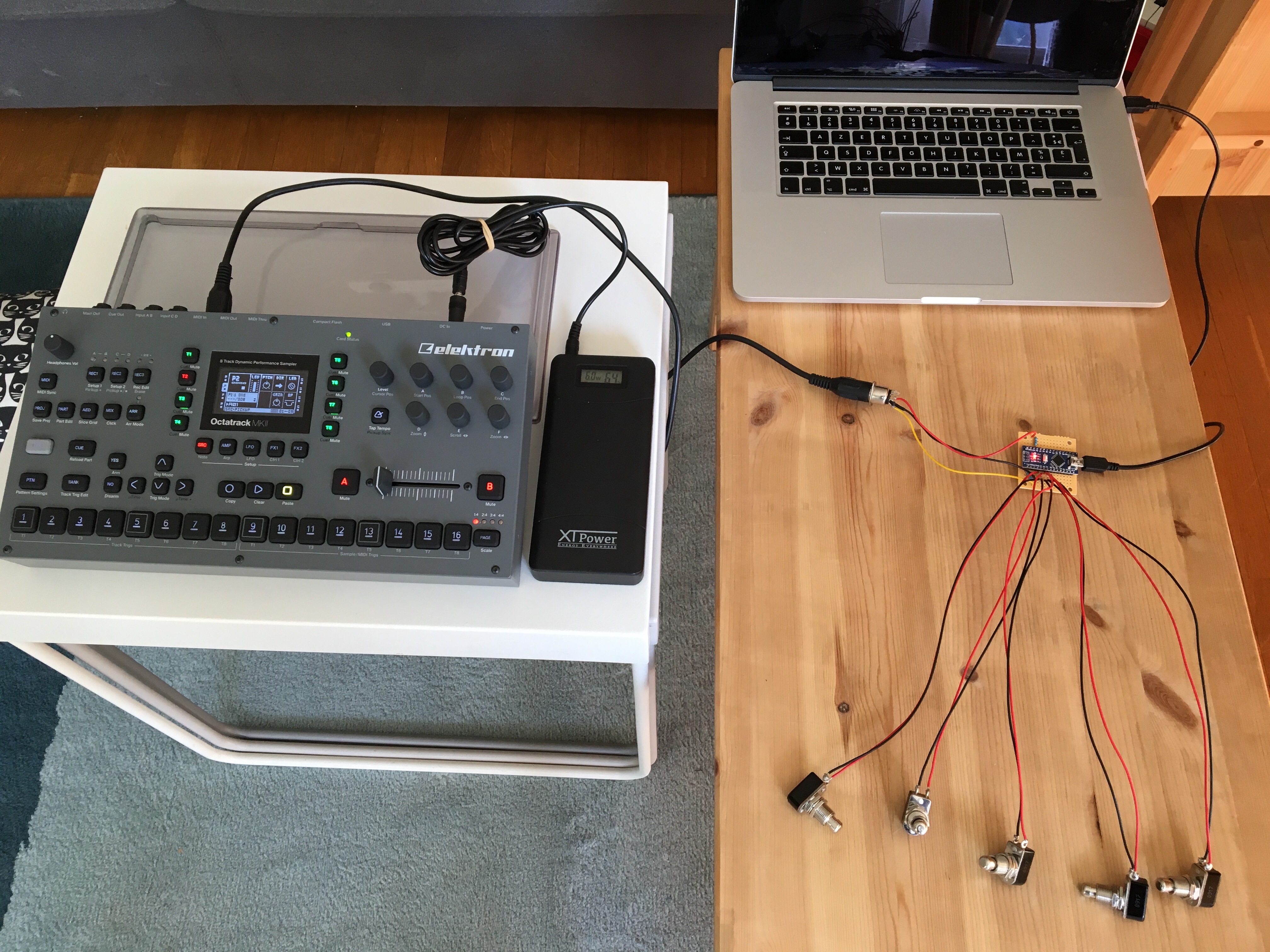
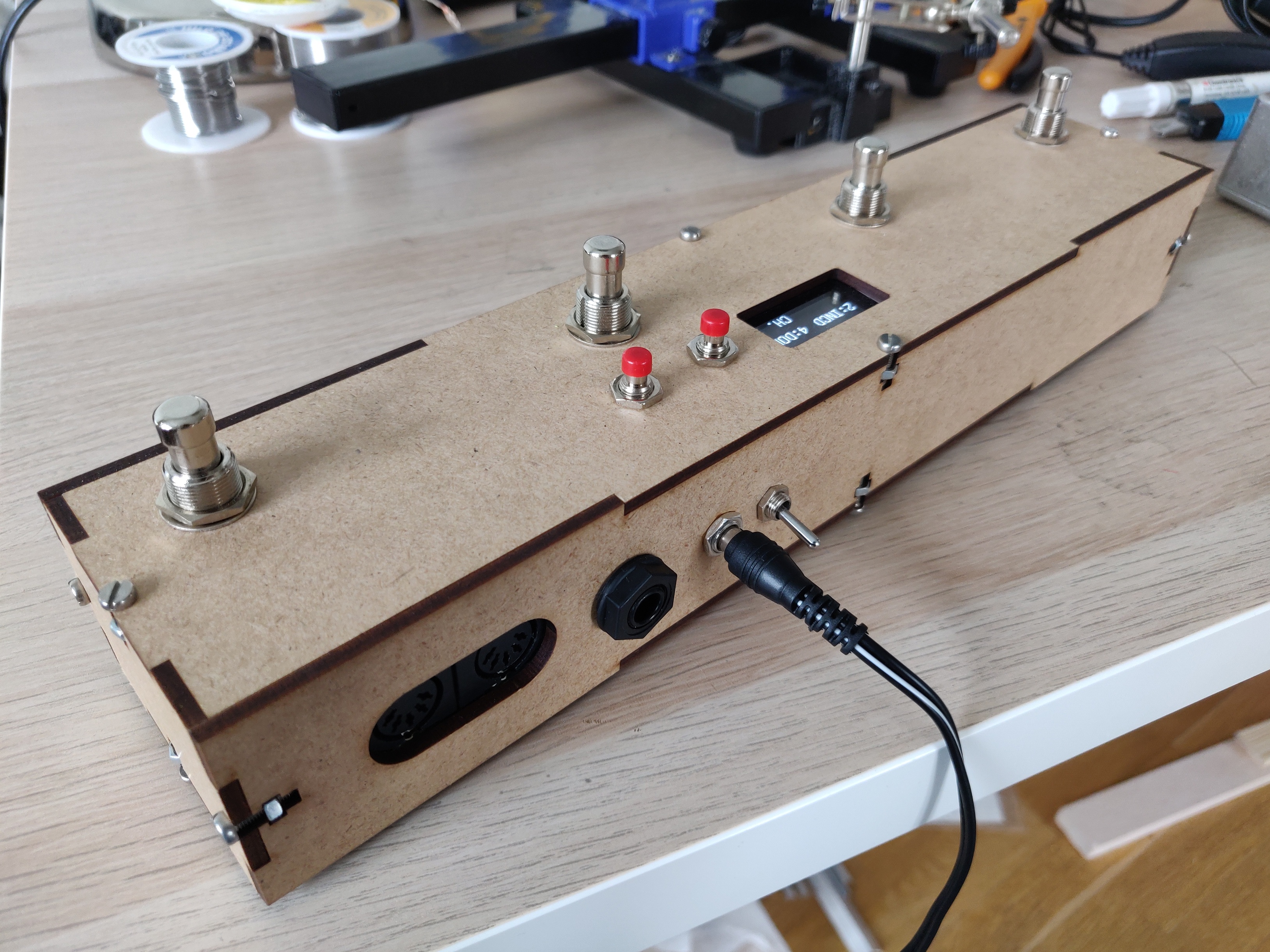
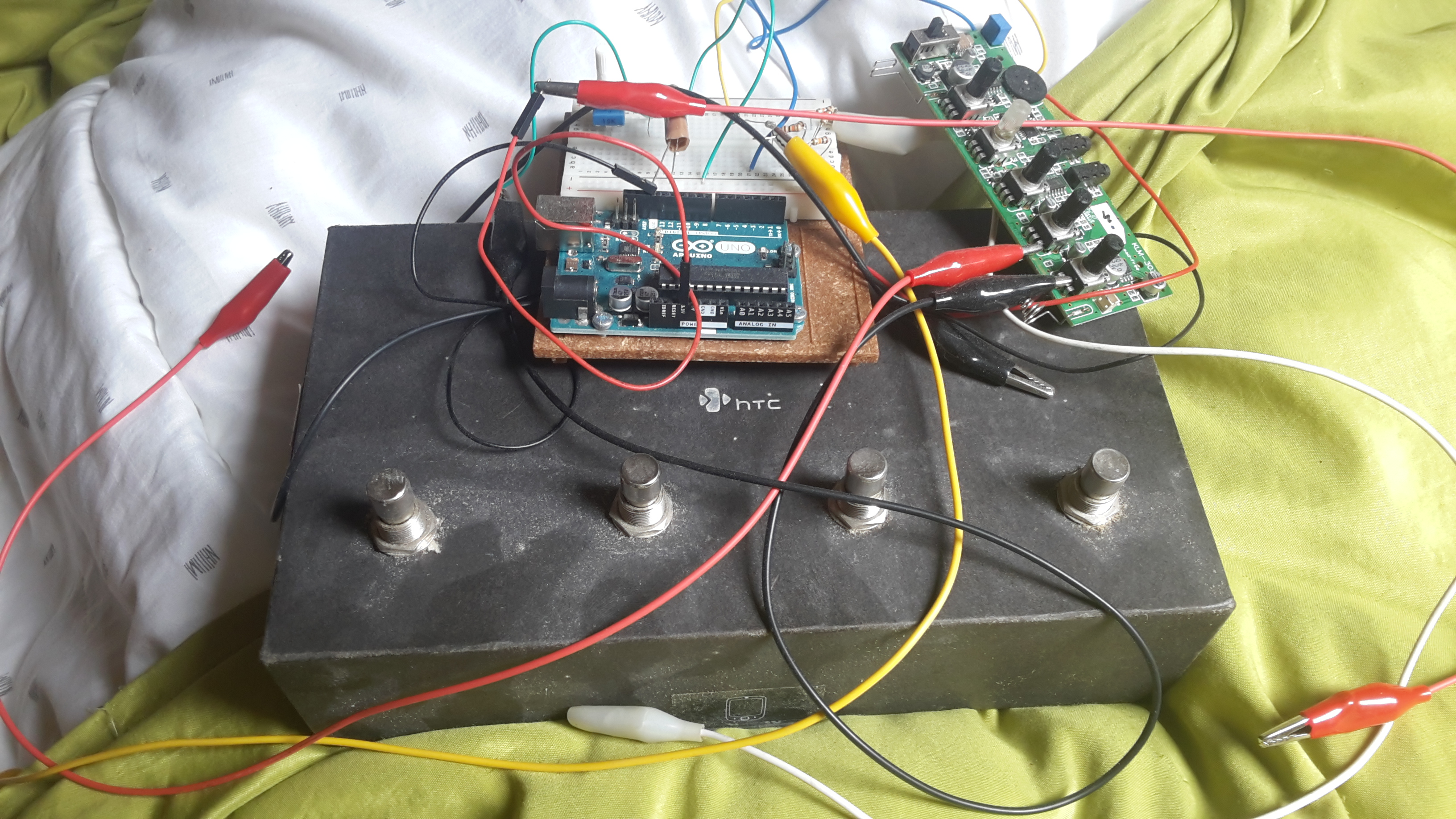
DIY: OT Pickup Machine footswitch (now with final pics!)

— EDIT: pics of the final controller :slight_smile: now with MIDI in, expression pedal input (converts it to MIDI CC), a display and buttons to change presets on the fly!
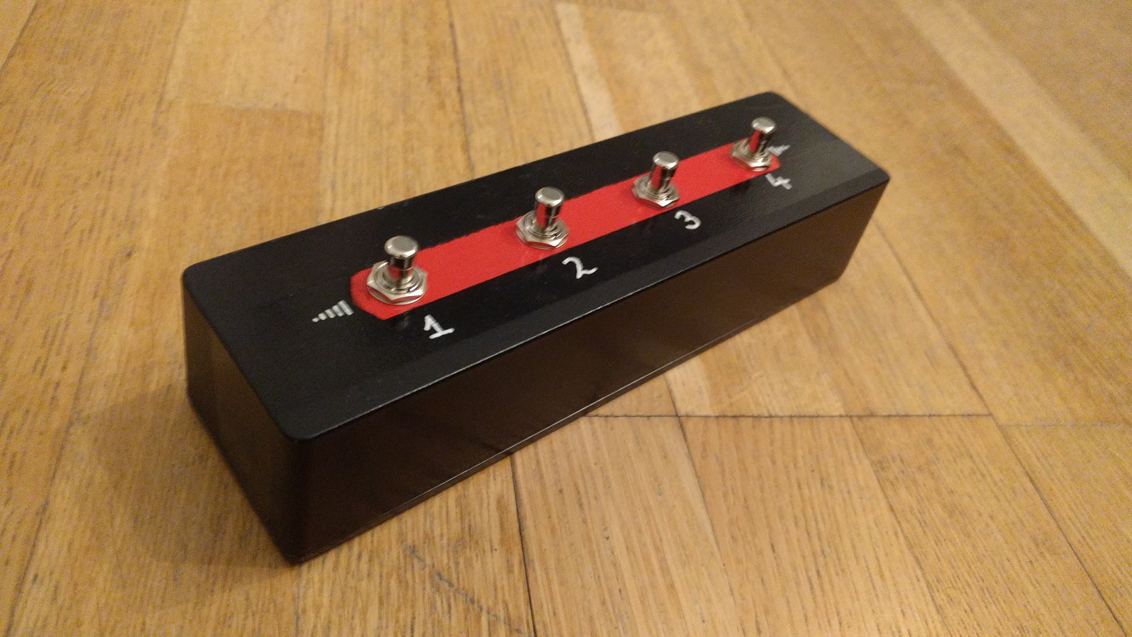
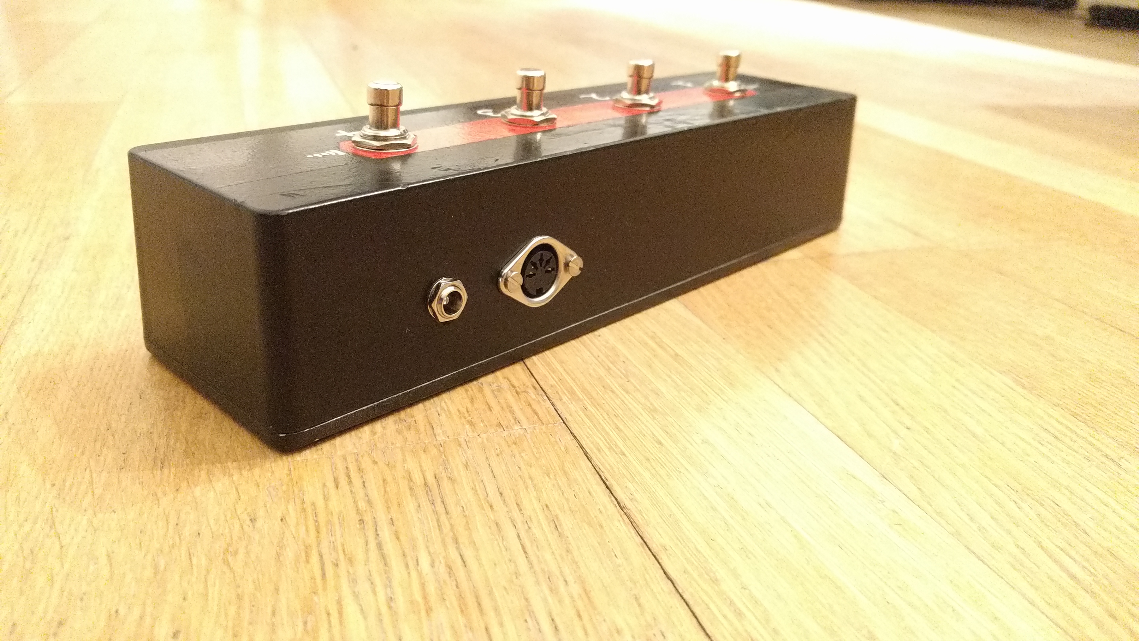
Previous iteration:

— Back to original post:

Hi everyone!

I loved my Digitakt since we first met, but I quickly missed the ability to play piano and guitar to my beats. I recently got an OT, and the first thing I tried to do was to learn how to use those Pickup machines. In order to free up my hands and loop with my feet, I came up with a quick arduino sketch to solve the problem without having to buy a huge footswitch board. This is my first ever arduino project (besides the teaching examples), so if I can do it, anybody can. Some things stated in this post might sound obvious, but I am trying to write clearly for people with little to no experience with electronics, as has been my case putting together this circuit.

Disclaimer: although I have tried to follow the MIDI association standard for MIDI out reasonably (just missing the double hex inverter/buffer after TX and the ferrite beads, both are optional in the specs), with homemade electronics things could go wrong. I take no responsibility for anything that could happen to any equipment from the use of this circuit. That said, I have tried it with a Korg Monologue, a Focusrite 2i4 into Ableton, and the OT MKII, and it works perfectly fine in those 3 scenarios.

Here is a scheme of the circuit, original picture from https://www.arduino.cc/en/Tutorial/Midi

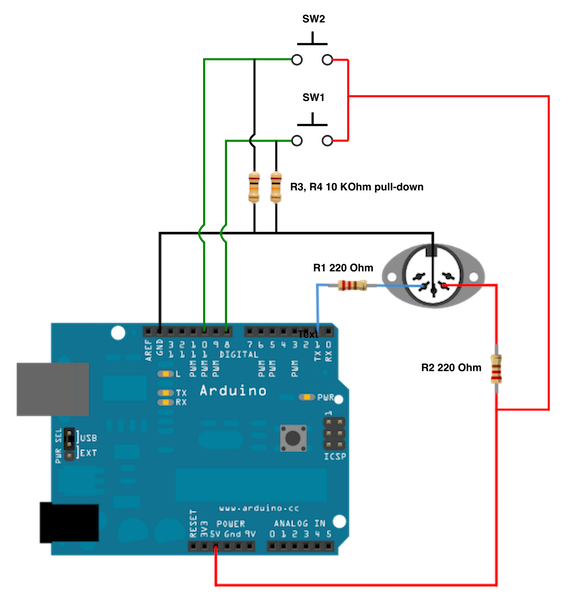
I have used the wonderful MIDI library from Francois Best to deal with the midi messages, which are sent on channel 14, same as the OT autochannel in my case. Instructions to install the library can be found in https://playground.arduino.cc/Main/MIDILibrary

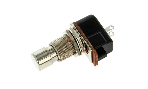
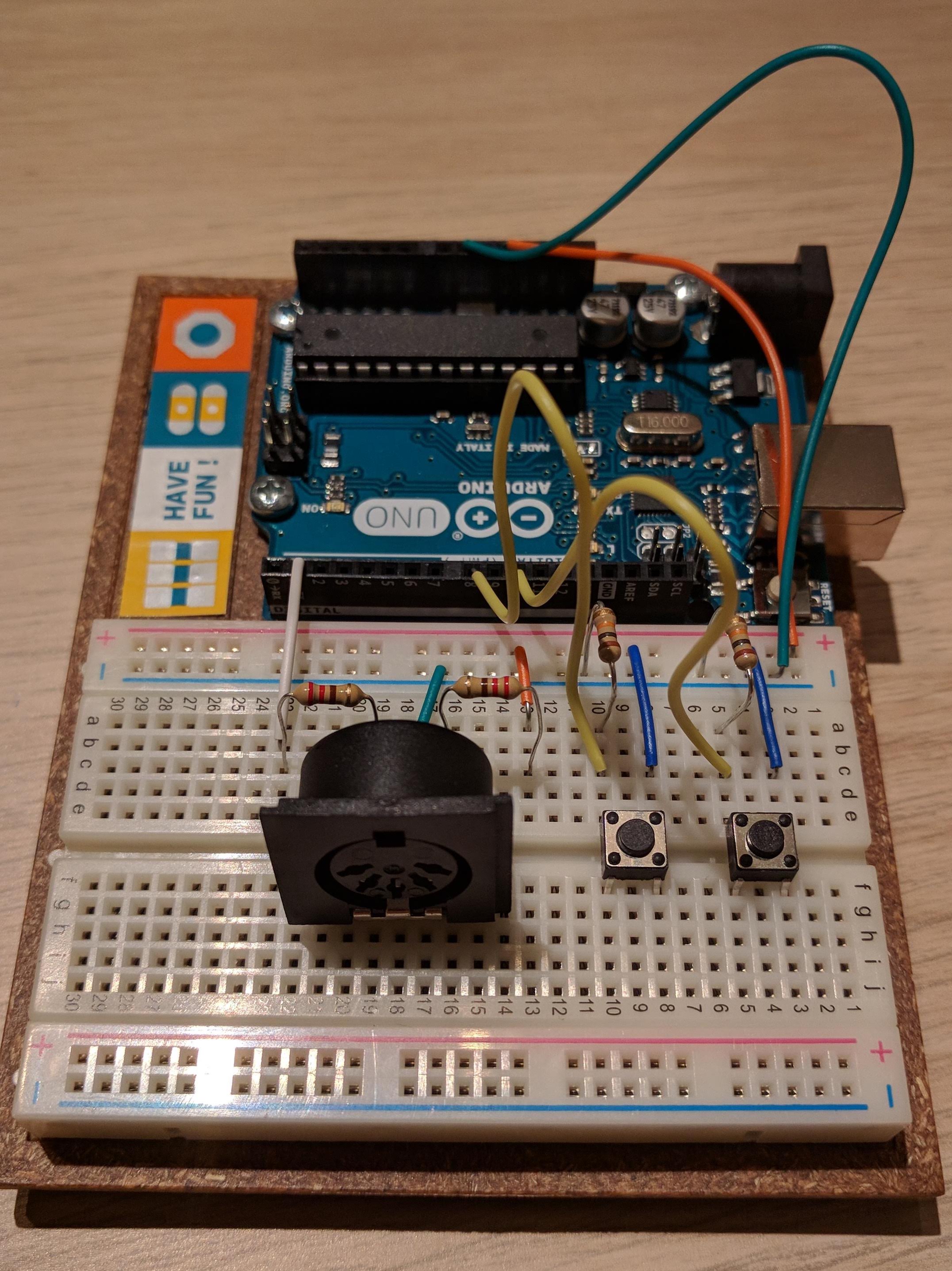
  • When SW1 (leftSwitch in the script) is pressed, digital input 8 registers 5V voltage, and the board sends a MIDI NoteOn 61 message (C#, registered by the OT as ‘INAB rec’). I have set 500 ms of wait time until the next message can be sent for debouncing, or making sure you don’t send two notes after each other if you press the switch for too long.

  • SW2 (rightSwitch) does the same with digital input 10, and sends MIDI NoteOn 62 (D, registered by the OT as ‘INCD rec’).

Here is the (very simple and short) script:

octatrack_midi.ino (687 Bytes)

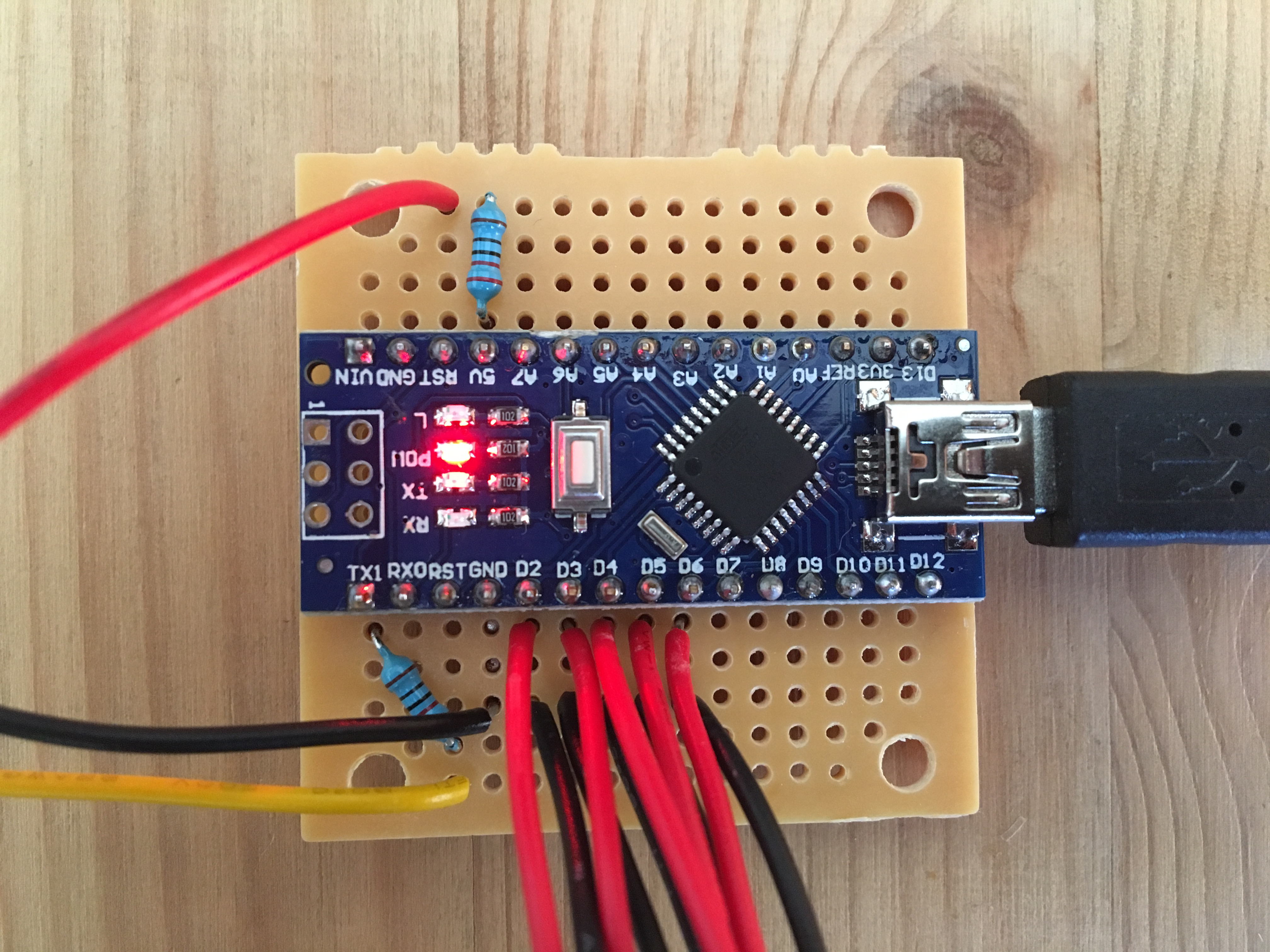
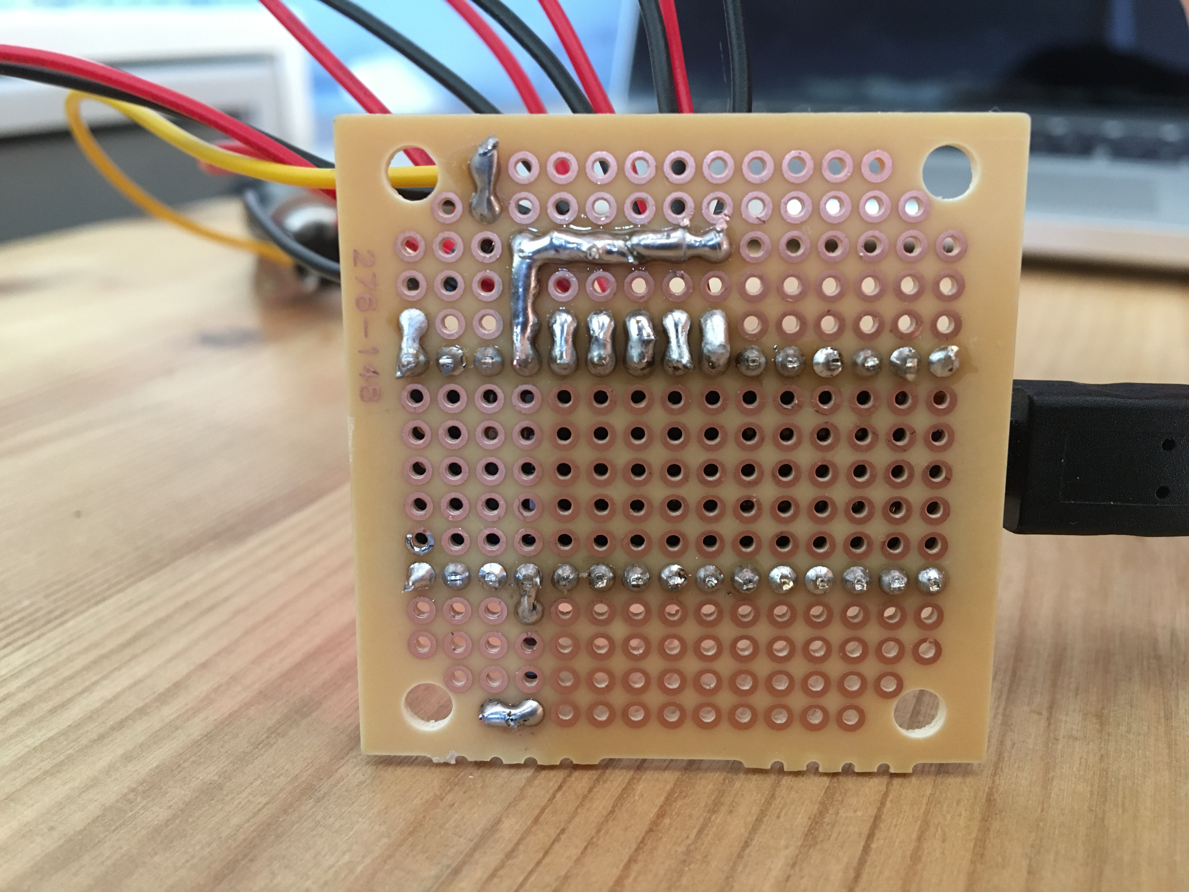
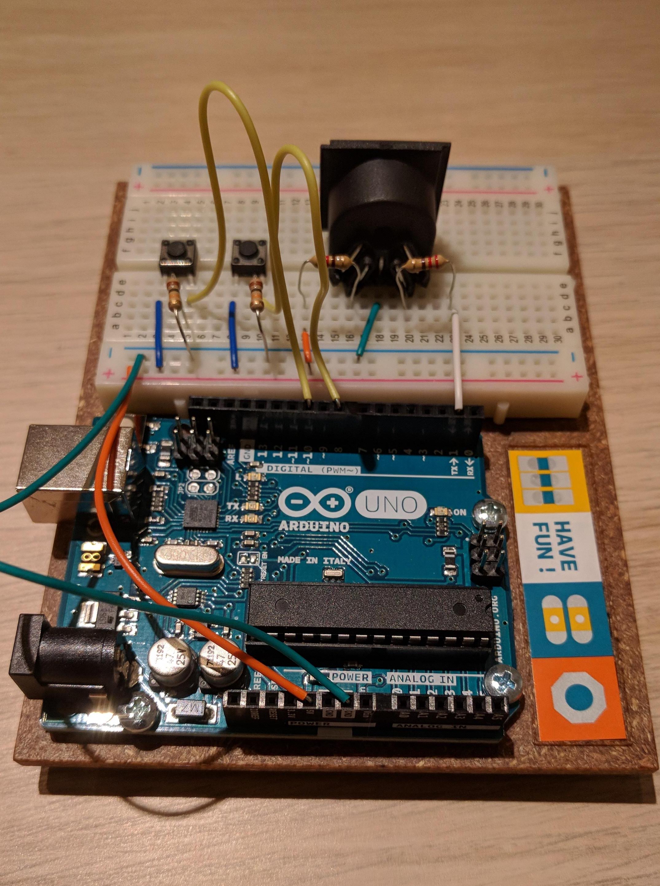
And pictures of the prototype board:


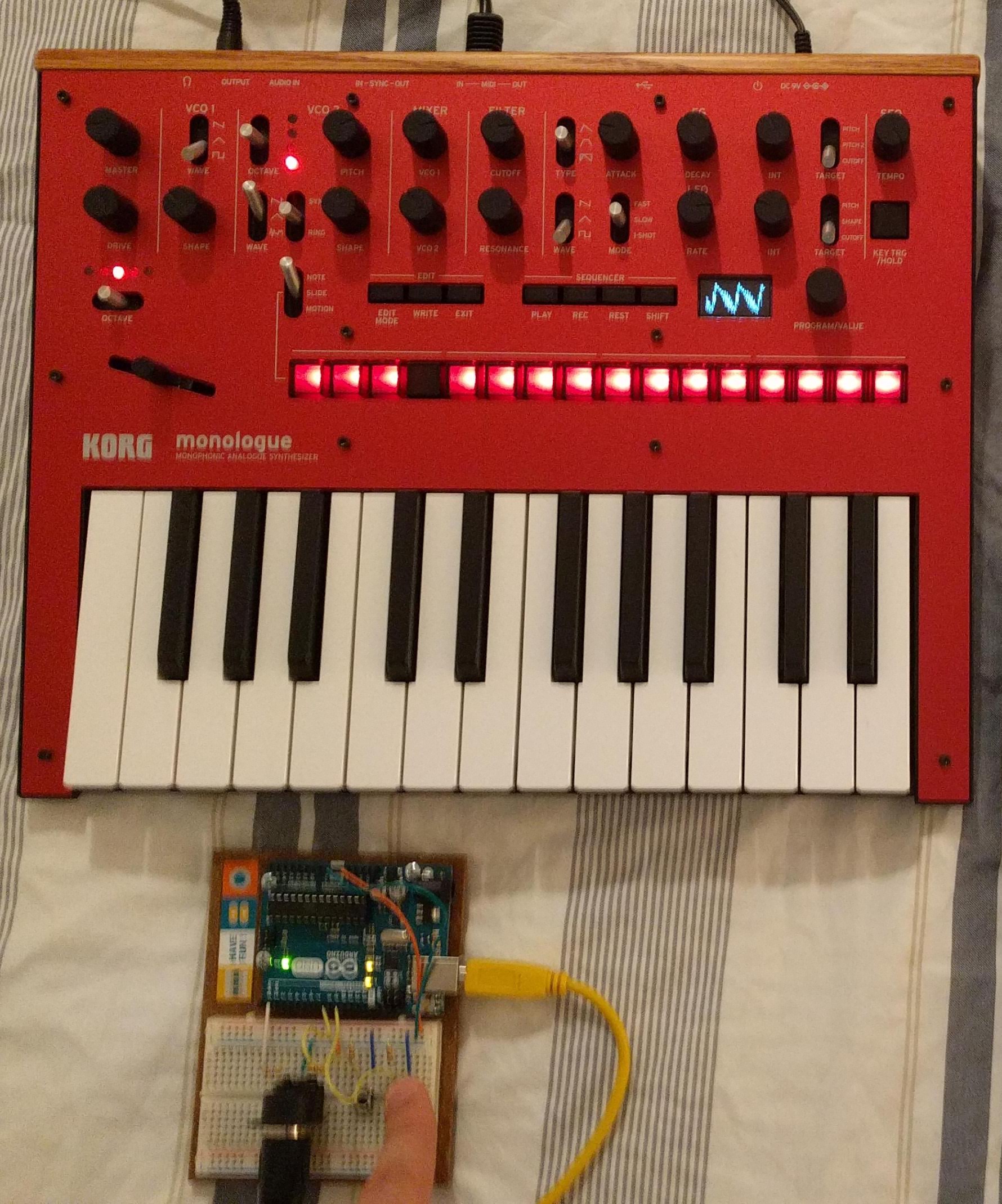
Here is a picture of the board next to the monologue, you can see the oscilloscope on while I press the switch. It works!

Hope this is helpful to some of you! I decided to post my experience with it after seeing some interest in DIY footswitches around here recently. I will post some pictures of the final enclosure once the momentary footswitches I ordered arrive!

EDIT: resized images for visibility.

EDIT 29/10/2018 after finishing the project:

Checking the code from @qlamerand as well as this link helped a lot with coding the behavior of the switches: http://www.gammon.com.au/switches

In case anybody wants the final sketch, here it is. Remember to modify it to suit your setup! Also, I do realize a lot of this can be accomplished with loops, but I explicitly coded every single switch for it to be more readable to anyone without experience in C.

octatrack_midi_4.ino (1.6 KB)

15 Likes

You got small feet ! :smile:

Good work, thanks, seems very simple, I’ve got everything to try it ASAP, including 10 footswitches ! :thup:

4 Likes

haha indeed it’s not very useful at the moment, really looking forward to the arrival of the footswitches! Please share a picture when you put it together!

2 Likes

Where can we get the midi library MIDI.h?
Seems really simple !

#include <MIDI.h>
MIDI_CREATE_DEFAULT_INSTANCE();
int leftSwitch = 0;
int rightSwitch = 0;

void setup() {
// put your setup code here, to run once:
pinMode(8, INPUT);
pinMode(10, INPUT);
MIDI.begin(14);
}

void loop() {
// put your main code here, to run repeatedly:
leftSwitch = digitalRead(8);
rightSwitch = digitalRead(10);

if (leftSwitch == HIGH) {
// send MIDI left, INABrec = 61
MIDI.sendNoteOn(61, 100, 14);
delay(500);
MIDI.sendNoteOff(61, 0, 14);
}
if (rightSwitch == HIGH) {
// send MIDI right, INCDrec = 62
MIDI.sendNoteOn(62, 100, 14);
delay(500);
MIDI.sendNoteOff(62, 0, 14);
}
}

1 Like

Instructions in here: https://playground.arduino.cc/Main/MIDILibrary

It’s dead easy, and you can change the MIDI message to whatever you want. Also very easy to scale up with more switches and more functions!

2 Likes

Ok I’m finished. Dead easy indeed. :smile:


Smartphone box with switches I made before

3 Likes

My two cents as I’ve been working on this these days :
There are two minor changes you need to do in your code.

First, this will send midi note as long as your button is pushed. To do it only at the first change from LOW to HIGH you need to save the previous button state and compare it to the new one.

Then, if you use footswitches like the ones I bought image you will need to debounce https://www.arduino.cc/en/Tutorial/Debounce. At some point when you push the switch, it will “flicker” between LOW and HIGH before it reads a real HIGH.

2 Likes

Hey @qlamerand, waiting for your answer on AF ! :wink:
I bought very similar switches at Thomann so thanks for informations !

What is debouncing ?

1 Like

Yes sorry, I will answer on Audiofanzine, I promise :slight_smile:
Debouncing is basically waiting a tiny bit of time (~50ms) just to be sure the value you’re reading is the one expected

1 Like

Thanks for your input @qlamerand!

The current debouncing plan is the 500 ms delay after sending the MIDI note. It’s not optimal, but for the purpose of the Pickup Machine it works. But you are right, the ideal way would be to remember the state of the digital input on the previous run of the loop, and debounce as well.

@sezare56 if I’m not mistaken, debouncing means making sure that your input on the footswitch is read only once, since when you press a momentary switch the circuit is repeatedly opened and closed for a short amount of time, risking sending multiple midi notes instead of only one in this case. This is why I placed the 500 ms delay after the first HIGH is read by the digital inputs.

Yeah the 500ms delay can work only if we press the switch for less than 500ms. This is not a big deal.
The other issue is if we wanted to click quickly multiple time as we could for a select next/previous track, each “click” will have to be spaced by 500ms minimum to be detected.
I will post a sample code (another promise) later.

1 Like

That’s a good point. If I end up implementing active track up/down switches, a shorter debounce would be nicer in the case of those (somewhere between 50-200 ms perhaps?).

I feel like I have not been using my OT enough to understand which things I would like to do with my feet. Perhaps once I have the ‘INAB’ and ‘INCD’ footswitches I will find out!

1 Like

oh perfect, I was just looking up / asking around for something like this the other day.

thanks for sharing!

3 Likes

Yeah usually it is very complicated with useless code!

debouncing is/can be something needed with most of the switches out there. it can be achieved either in software or hardware, depending on the needs and the way it is handled can vary depending on the switch used as each switch is different from another and could ‘bounce’ more or less than another. although a simple delay does help in reducing the risk of wrong readings, it is not always enough to make sure that things work as expected.
there’re few articles on the subject which can help find the best solution for a specific cirtcuit/switch. for simple code that is supposed to read few switches, adding a belay between each read should be ok, but one has to consider that each software delay added to debounce a switch, will also slow down the code a bit

4 Likes

So here is my code with proper debounce. I use 5 footswitches and the internal pullups for all of them, so the logic is inverted but it’s an economy of five 10k resistors :slight_smile:.
I’ll post pictures later.

#define OT_AUTOCHANNEL 10
#define BTN_COUNT 5
#define BTN_START_PIN 2
#define DEBOUNCE_DELAY 50

int notes[BTN_COUNT] = {60, 64, 68, 69, 71};

int buttonState[BTN_COUNT];
int lastButtonState[BTN_COUNT];
unsigned long lastDebounceTime[BTN_COUNT];

void sendMidi(int b1, int b2, int b3) {
  Serial.write(b1);
  Serial.write(b2);
  Serial.write(b3);
}

void noteOn(int note, int velocity, int channel) {
  sendMidi(0x90 + channel, note, velocity);
}

void noteOff(int note, int velocity, int channel) {
  sendMidi(0x80 + channel, note, velocity);
}

void setup() {
  for (int i = 0; i < BTN_COUNT; i++) {
    buttonState[i] = HIGH;
    lastButtonState[i] = HIGH;
    lastDebounceTime[i] = 0;

    pinMode(BTN_START_PIN + i, INPUT_PULLUP);
  }

  Serial.begin(31250);
}

void loop() {
  for (int i = 0; i < BTN_COUNT; i++) {
    int reading = digitalRead(BTN_START_PIN + i);

      if (reading != lastButtonState[i]) {
        lastDebounceTime[i] = millis();
      }

      if ((millis() - lastDebounceTime[i]) > DEBOUNCE_DELAY) {
        if (reading != buttonState[i]) {
          buttonState[i] = reading;

          if (buttonState[i] == LOW) {
            noteOn(notes[i], 127, OT_AUTOCHANNEL);
          } else {
            noteOff(notes[i], 0, OT_AUTOCHANNEL);
          }
        }
      }

      lastButtonState[i] = reading;
  }
}
3 Likes

…standard MIDI baud rate is 31250, maybe worth changing/checking this one unless of course it’s all working fine :slight_smile:

2 Likes

Oh yes of course, sorry for that. I’ll edit my post.

2 Likes

And another edit (inverted note on and note off command codes). Sorry for all these typos.

2 Likes

My work bench :wink:


And another edit of previous post containing code (the autochannel was wrong).

7 Likes