Any interest in a DIY sequencer project?

This is something I’ve been working on recently. This is the brief I set myself.

Small format - small enough to work as a eurorack module

Minimal control count - ties into the need to keep it small

Minimum of 16 steps - expandable or a facility to chain more than one sequencer

No microcontrollers allowed - for the DIYer who isn’t a programmer

Off the shelf and easily obtainable components - mInly built around CMOS logic DIP parts still in production.

Low parts count - no brainier as long as I can get the functionality right.

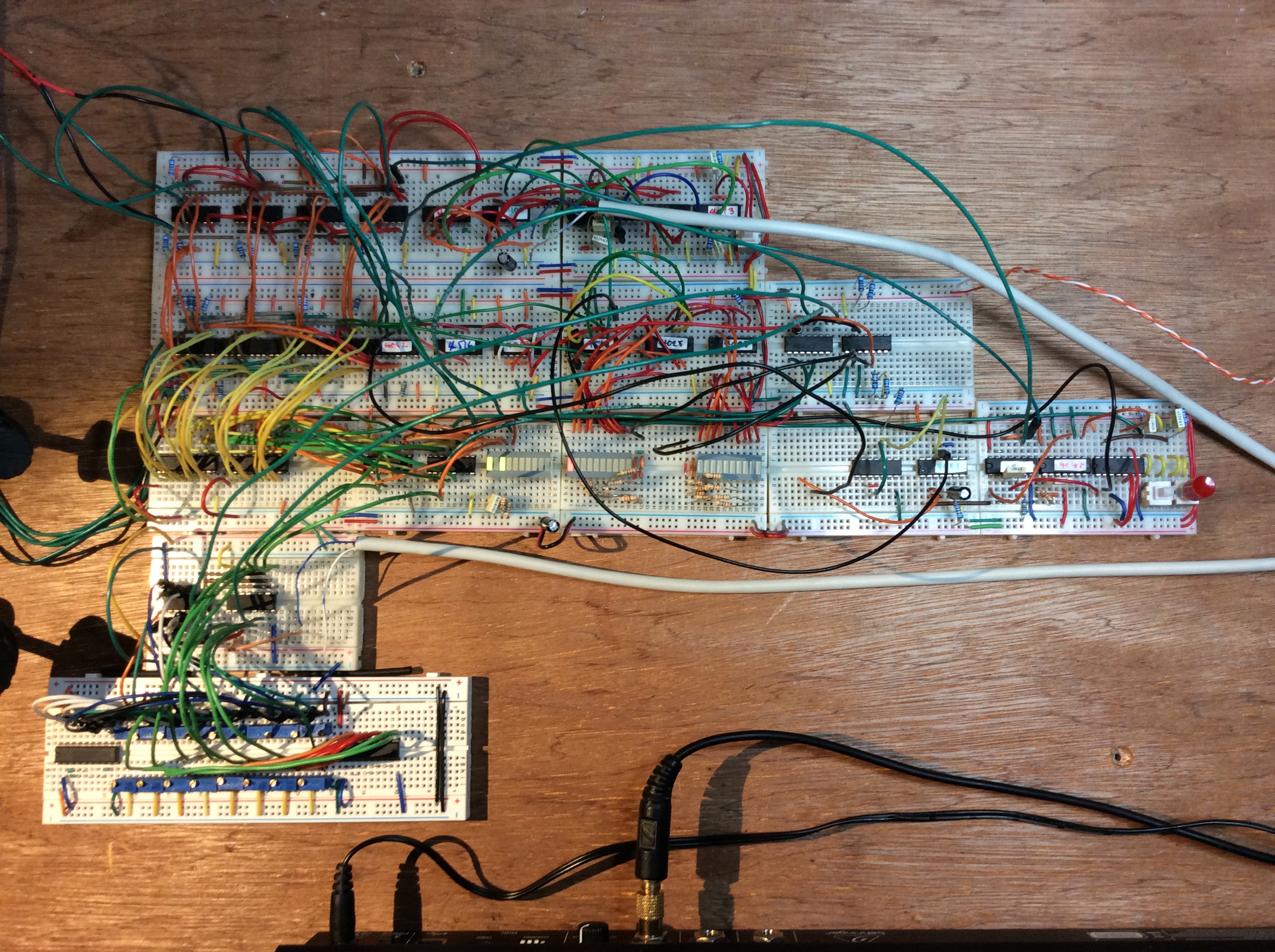
So far I’ve made good progress. I’ve got the heart of the sequencer breadboarded and running. Currently working on the control and interface side of things. Sequencer outputs quantized note cv’s across just over an octave. Octave shift per step is intended as well as ratcheting (up to 4 gates per step), sync output at 24 and 48 PPQN as well as pulse per step. There are a few other things I’m hoping to implement. I’ve got them roughed out but not prototyped yet.

The unit will be fairly spartan with just 4 controls for setting the 16 notes, play and programme modes with start, stop and record (programming mode) controls. If I add, say another set of 4 parameter knobs I can control more per step setting but then I’m up to 8 knobs and the eurorack footprint will be getting wider. I could possibly implement those extra per step settings with push buttons.

This isn’t a MIDI sequencer as there is no processor so it’s purely a CV and gate sequencer and a quantized one at that. Obviously the output doesn’t just have to hit a VCO tho.

Without getting into mission creep I recon I can implement ratcheting and per step gate length settings but there is the trade off with the controls. I’m imagining a clean and logical workflow rather than a ton of knobs. It’s a trade off but I feel there’s a happy medium to be struck.

What do you guys think? I know it’s a million miles from some of the midi sequencers on the market but it’s not aiming at competing with them, it’s more a small and easy to programmme little DIY box for sequencing short patterns but offers something more than a 4017 based sequencer, another DIY favourite, such as quantzing, more steps and less real estate as less controls are needed.

2 Likes

16 steps with rachetting, thats cool. Would be nice if appart from pitch (slides please) and gate it could have 2 more lanes, like velocity or modulation (with slides too)…and do not forget about reset …:sweat_smile:

My simple cv sequencer is the korg sq1 (very fun), but I also use novation monostation …

I’ve not prototyped the ratcheting element yet but I’ve it drawn out and I’m confident it’ll work. Like everything it’s then getting that functionality available through the controls. I’m always conscious of adding more controls to the front panel as I’m getting further form my own brief. The other issue is for another lane of sequencing I would essentially need to double up on the sequencer core. No biggy but again I’m moving away from the minimum parts count. These are things I’m gonna have to weigh up. If it’s worth it I’ll do it.

Regarding slides the only way I can envisage doing that is to have a slew generator sat on the CV output. If I could find a way of gating the slew generator on and off per step which shouldn’t be hard that should be doable. I’d have to do some research into SG’s.

Reset is something I’ve been mulling over. I’ve got a couple of ideas I need to breadboard first. At the moment I’ve just got a push button set up to reset the counters to 0. Interfacing that won’t be an issue, the thing I’m trying to work Through is how that reset interacts with the CV generating digital bits I’ve already got worked out.

Thanks for the feedback.:+1:

2 Likes

More rationalisation on the Control front. They’ll be a couple more knobs and switches but not many. Mission creep is kicking in and I’m mulling over whether to package it with upgrading in mind as in designing some way of being able to add extra boards for extra steps… I’ve not decided yet.

Ill with crappy breadboards that were causing me untold grief (and needless re designs) I re jigged the prototype. It looks mammoth at the moment and I’ve still not started the analogue board yet but I’m fairly confident of getting it all on two boards. We’ll see…

5 Likes

Roughed out the core bits on the analogue side last night to prove it would work and it does so happy days there. I’ve had to order some bits so I can tidy some stuff up (I can lose prob 4x 40106 inverters by using a couple of octal non-inverting buffers for example) and so I can start finalising things.

1 Like

I was looking at this. https://bastl-instruments.com/instruments/omsynth/ to do this.
https://www.youtube.com/watch?v=t7JYOIYqMEY. Long term, I’d like to understand (broadly) how Dave Smith designed his sequencers.

The reason is that I want to sequence a struthi. But since the economy took a turn, I’m going to try to learn to do something similar in Pure Data.

But yeah, super neat.

1 Like

I’m not au fait with how DSi implement their sequencers. The Evolver from memory has two PIC chips that do all the processing including the sequencing software. My project is strictly CV output. No midi or micro’s used

If you’re interested in studying how micro’s run hardware and sequencing you could take a look at the service manual for something the the TR808. Those early Japanese service manuals were pretty comprehensive in terms of giving detailed descriptions. It’s interesting to see how it was done back then and it acts as a good learning tool.

2 Likes

Awesome, thanks for the info. I definitely wouldn’t have thought to look there.

1 Like

Roland were pretty good in that regard. Same with the earlier Jupiter 4 service manual. Some of the translation leaves a bit to be desired, especially in the earlier manuals but you can get the idea.

Had a look at those links. The diy kit looks handy is you’re a beginner in so far as you get a few handy bits like a power supply, audio amp, some breadboard etc. I can see he’s using a scope kit, another bit of kits that’s super handy. I used CRT scopes for years but recently bought a Rigol digital scope. Those kits look cool if you don’t want to invest in a proper bench scope. You needn’t spend fortunes on bench gear. You can get older used power supplies and scopes on places like eBay. Some of that gear would have cost a small fortune when new and at the end of the day is made for the job. A small regulated circuit on a board won’t offer the same standards of protection and smoothing that a bench PSU will.

One tool I’d say is indispensable is a logic probe. A cheapo will do fine and I find i use mine as much if not more than my scope.

Those chips he’s using in the video, the 4040 and 4051 belong to the CMOS digital family. The other family is called TTL and the two types aren’t usually interchangeable. To confuse things further you can get CMOS chips with part numbers very similar to the TTL equivalent so for example a 74HC193 is a CMOS chip. The 74HCT193 is the TTL version. Different manufacturers used different naming practices too so a Texas CD40175 would be a 14175 from Motorola (and also a 74HC175 from Texas too!) My advice would be to choose a family to study (most folk choose CMOS these days) and start doing some reading. If you’re a book person have a look for some beginners guide to CMOS logic or something similar. You’ll find tons of info online too. Have a look for Lunetta’s too. Stanley Lunetta used to write books on Logic circuits I believe and his name got co opted by folks using (and more commonly abusing) logic chips for making crazy devices for making music. The whole Lunetta thing was popular a few years ago, maybe still is? Logic is fairly easy to understand and from an electronic point of view is much easier to learn than linear electronics. You’re dealing with on and off, 5v or 0v. If you can get your head around And, Or, and Not and understand a timing diagram you’ll be away.

Let us know how you get on. DIY electronics is a great hobby, especially for long days stuck indoors!

So I’ve got the sequencer up and running and playing the Neutron. So far I’ve got…

16 steps which can have

16 discrete CV values selectable by a rotary switch.

Each step can have a mute (no gate), a single gate or x2, x4 or x8 gates per step, sort of ratcheting if you like, again selectable via a second rotary switch.

Each step can apply a division factor to the internal cv select clock such that you can effectively divide the clock that selects the notes independently of the gate clock. In conjunction with the gate multiplier this should allow for patterns that appear longer than 16 notes. (I’ve not implemented it yet but it’s effectively the reverse of what I’ve done with the gate). I can only divide by 1 at the moment unless I reduce the number of clock multiplier options… it’s a trade off for spare bits!

It’s just a case of corralling everything under some control, tidying up etc.

There’s a lot of circuitry going on; the core of the sequencer consists of 14 chips alone. The control logic and gate generator is another 15 (and counting) and 4 for the primitive DAC. It’s starting to feel like on of those Victorian paintings of wondrous contraptions that do simple tasks… I could have written some code and programmed a micro (except I can’t code) or built one of the conventional CMOS sequencers. This is just a bit different and offers things they don’t.

:clap::clap::clap: very awesome!!

Following this thread with great interest, it’s really cool to seeing all this being done with out coding

1 Like

Progress report.

Some time ago I rescued an old bench top pH analyser out of the lab at work; it was destined for the weee skip so, as I tend to do, I chucked it in the back of the van for another day. It’s been gathering dust in the stock pile so the other day I decided to open it up and see what, if anything, I could salvage. The case is super funky so I pulled everything out of it and had a closer look at the main board. Usual affair of mask ROMs, a couple of processors and some ancillary chips along with a handful of TTL bits and bobs, thankfully all socketed too. Couple of standout parts, a 74LS154 4:16 line decoder, a DAC1006 and a new one to me, a HM6116 2k CMOS static RAM chip. I’ve never played with RAM chips before so I drew out a bit of a schematic hoping to integrate it into the project somehow… would I be able to save more than one sequence? Could I get the thing to actually work? The data sheets I could find are fairly simple affairs so with a bit of head scratching I spent most of the day on the breadboard.

So now I’ve got 128 pattern memories!!!.

I need to tidy up the circuit a bit and get the whole write/read process a bit more automated but that should just be a couple of logic chips. I’m buzzing! Not tried roughing out a battery back up yet but that shouldn’t be hard? As long as I observe the correct sequence on power down/up.

1 Like

this looks like a proper modular, not like those off-the-shelf eurorack charlatans :face_with_monocle:

1 Like

He he! Cheers. Irony is I’ve not got a modular😂 I do intend on getting a small system going at some point tho.

Funky case sans innards. Begging to be upcycled…

The upper part flips up…who doesn’t like flip up front panels? :joy:

2 Likes

After experimenting I’ve had a radical redesign. Using SRAM I’ve been able to sack off loads of circuitry simplifying the layout and reducing parts count! Added bonus include the improved features such as more memories. I’ve been trying to get a prototype layout sorted too. There are a few controls to add (the knob for the gate logic is there but it’s not connected; it’s all tested and working tho) just the core of the note sequencing.

I’ve not thought much about the analogue side; at the moment I’ve got 16 multitude presets that set the discrete voltages per step. Works fine.

The digital side of the gate generation is sorted but for a bit of finishing on the control side. So far it’s set by a 5 position switch with settings for mute, gate, gate x2, gate x4, gate x8 on a per step basis for ratcheting/repeating etc. The master clock (which selects the note data sent to the DAC) will have a division factor independent of the gate multiplier for ‘stretching’ pattern note data past 16 steps. I might be able to incorporate that on a setting per step basis too but I might have to sacrifice that as the bit count is maxed out. Might re jig. One bonus is that the way the design works you’re just saving bits per step…those bits can control anything but can also be as wide as you need as long as you don’t exceed the 8 bit limit. To get around that would require shift registers and make the control side more complex… it would be easier just to ‘break into’ more SRAM.

Old design

New design.

Knobs are for setting note and gate value respectively. Red button toggles programming mode, green is reset and black is advance step. So it’s a case of select prog mode, set up your note and gate values, press advance and repeat until all 16 steps are programmed. Toggle back out of prog mode and the advance button doubles as play.

Point is that’s all gravy, the basic principle works and is tested. I’m messing about with old pulled SRAM chips but looking at current data sheets tells me my basic design will work with them too. I’ve been rooting about in the stock pile and I’ve found a few more chips, one that, if I swap it out with the one I’m using, should give me 64 steps per pattern, basically with the addition of a couple more logic chips. Don’t you love being green?:joy:

1 Like

Wallace and Tiernan Chlorine controller dragged out of the WEEE skip today. The case is begging to be re-purposed… it even looks like some behemoth from the 80’s with that Prophet VS colour scheme and a huge VFD display! :slightly_smiling_face:

1 Like