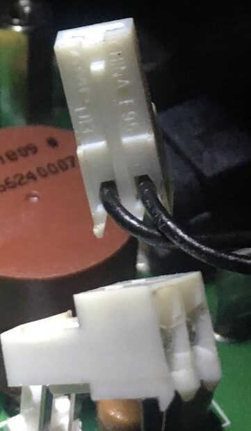
I have narrowed a problem with my elektron machinedrum down to the power switch and/or the cables between. The power switch I have located on element14 to replace (arcoelectric H8550VBACA rockerswitch https://au.element14.com/arcolectric/h8550vbaca/switch-dpst-10a-250vac-black-i/dp/273200), but the problem seems to lie with the cables and or the crimp connector. Does anyone know how I can locate these particular crimp connector?
How did you determine the cable is faulty? I don’t see any damage. Cables seldom go bad without a reason (like overheating). Have you tried just unplugging and replugging them?
If it is the cable there’s probably a loose connector contact. Those connectors look like they are crimped on the wire, you could check for loose contacts in the connector. Have you tried testing them with a multimeter?
I’m assuming you checked continuity at the switch and theres no power on the “on” side of the circuit regardless of which direction the switch is flipped. If the switch is actually bad I would also assume you can smell the “burnt component” smell when giving it a sniff test. It’s very unlikely the molex connectors are bad, the wires aren’t fusible links so unless they were cut or under some trauma indicated by melting or other physical indication it’s also unlikely they are bad. If you want to verify the switch is bad, remove it and use the switch in an independent circuit with a battery, an appropriate resistor, and an LED light - if the light will not light when you flip the switch, then you’ve confirmed the switch is bad. If you confirm the switch is not the problem, at that point you’re looking at components around the switch that limit or would inhibit current, and if it’s not the wires/connectors then you’ll need to be really careful because something will probably need to be soldered at that point.
You could similarly (at your own risk, FOR TESTING PURPOSES ONLY) plug the MD into a surge protector in the OFF position, use jumper wires with spade connectors (or jumper wires with alligator clips) to complete the circuit where the switch would go (it’s not a fused switch, it just completes the circuit), then using the power strip as the on/off switch, you could temporarily power it on to verify whether or not the wires really need to be replaced. If you have a multimeter I don’t really think this is all necessary but just suggesting options so depending on your situation, you can figure something out.
I think it wouldn’t hurt to contact elektron’s support and ask if the parts are available for individual purchase, they no longer service MD’s but from what I’ve seen, the warehouse still stocks some parts.
If any of that seems out of your comfort zone, don’t do it, let a person with experience take care of it. This is all pretty straight forward though if you’ve already diagnosed it that far.
Yes - checked continuity. The positive connection is working, the negative is not. It stops working between the switches final terminal and the internal power supply of the machinedrum.
Currently the unit is powered on again, I just had a jam. but on several ocassions when I was putting it back together, once I realised the problem was with the power supply and cables, it would still not power on again. Thus my conclusion that there is something loose in the cable crimp. It is sporadic. Too much movement, some bend in the cable, not sure.
Here’s how I narrowed it down.
a) checked continuity between all points from the DC brick supply b) used arduino jumper cables between the two pins and bypassed the switch (which works 100% of the time)
Anywho, yes, contacting elektron is in process, Im just wondering if anyone here can help identify the cables as my post outlines.
The type of connector part - damn I totally did not write that correctly its been a long day of troubleshooting! I’ll edit the opening post, just assumed it was clear with the photos.
It’s totally understandable so not really an issue but being clear is important to get what you want, and specifically are you talking about the molex (plastic) connector part?
Maybe someone knows but we’re so far removed from the production of the unit that the part number isn’t likely to be very helpful. Hopefully support gets back quickly but if they are laggin my first move would be take some basic measurements then try to visually match the style on digikey or mouser electronics, then I’d check out the data sheets to see if the measurements match what I’ve noted. I wish I had a specific replacement part in mind if you think that’s what the problem is, but I would guess it’s more likely that the problem is inside the switch than the molex connectors themselves, unless something is grossly loose or there is some visible electrolysis on one of the metal spades or receiver parts in the clip or on the switch. Is there something that looks like it’s damaged? the pictures look ok but it’s not at a resolution where I can really zoom in and see.
However, I just have no categories or terminology for researching these parts. I don’t even really know what they are (motherboard crimps? crimp connectors?
As I recall when I had it open it did look like there was a bit of wear on the switch (a bit of brownish tint near the solder of the terminal) so maybe re soldering the cables could also fix it. I might try tomorrow
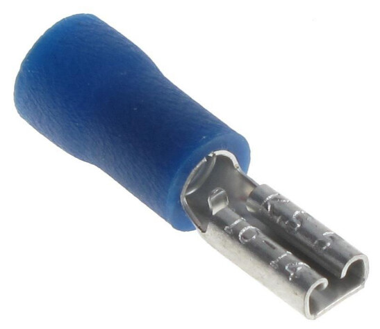
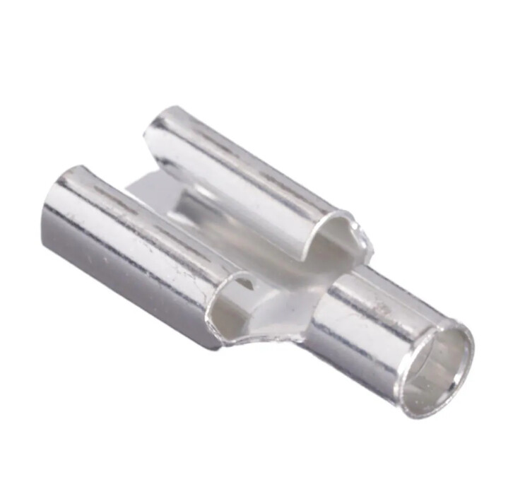
Before I started soldering I’d run a few bench tests on using the switch with a basic current limited battery/resitor/ LED circuit and see if you can consistently reproduce the issue just to confirm what the issue actually is. I hate doing it but I’ve taken apart switches of various kinds and repaired the internal tumbling mechanism when it was impossible to replace them, however I don’t think this is one of those cases. If you’re talking about the metal crimp ends it’s the female end of a crimp terminal, if the male end is flat it’s usually called a spade, if it’s round it may be referred to as a barrel. I don’t think it’s so specific of a thing, you would usually find that type of part used in general electronics or automotive applications, another source of parts might be a car stereo specialist as they often use similar molex and terminals, however I’m fairly certain mouser or digikey or possibly anyone should have something comparable but the size, of course, will be the key indicator of whether or not it will fit. Also if you intend to replace the wires, the wire gauge should be the same or greater (ie lower numbered gauge = greater size) but it seems like you already know that part.
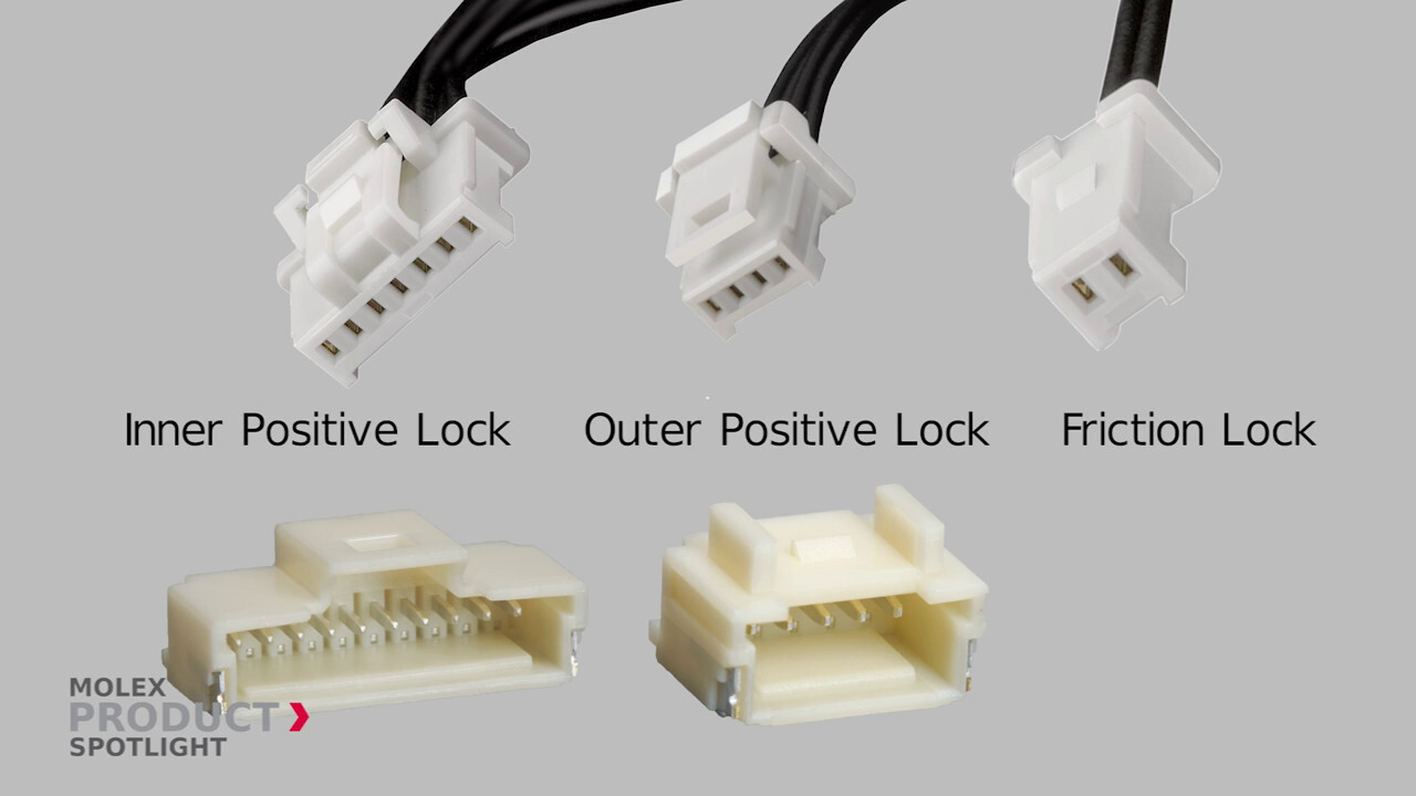
I can’t explicitly tell from your photo but the female end looks like this (approximately)?
I just searched “wired spade connector” and got a variety of hits
Here’s something basic about adding and removing pins (or in your case terminals) from molex connectors so you can re-use the connector and replace only the wired/crimp terminal parts.
Also search youtube for “remove molex connector pins” and about a billion hits come up. Should work out ok as long as you make a proper diagnosis, never fear.
sounds like the switch then no?
i’ve tried to follow your problem solve but agree with others would be a surprise if it’s the crimps/connectors.
common for the rocker to fail after some time/use.
does it click/feel right when you flip it?
Sorry Im just super confused by your post, I think it is completely missing what I am actually inquiring about and you’ve ignored the test I’ve already done to isolate that it is a problem with the cables and the switch (bypassing by using a pair of arduino cables).
I appreciate your effort but do not understand why the automotive cables are being suggested. Do you mean to suggest connecting these to the PCB pin headers? I know from just memory that these automotive spades are too thick to fit, and in this case DANGEROUSLY CLOSE. So completely unsure what you are really suggesting. If it were to attach it to the switch, I would need to unsolder the cables anyways (which you suggest "Before I started soldering ").
Very confusing, whatever you are suggesting sounds like way more complication and effort than reapplying solder with an iron.
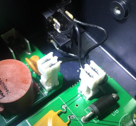
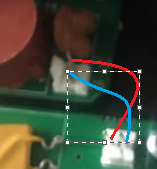
Since maybe you aren’t understanding what I’ve done to isolate the fact it is a problem with the crimp connectors and/or the switch, here is a photo of how I bypassed them with a new set of cables to actually turn the unit on reliably and consistently.
However, I WANT to be able to use the switch, which is what the meaning of my opening post is all about. So I am asking for what are the type of white plastic connectors used that connect to the pcb. In nowhere in my opening post did I outline I was having trouble troubleshooting it, as I spent an entire day looking over the unit already.
You seem very confident it isn’t the plastic crimp connection, but I could easily imagine an assembly failing to cut enough length to the exposed wire before entering it into the sleeve, and thus not making proper contact consistently. I’m not sure. I have no idea why it is not consistently reading continuity. All I know is that SOMETIMES am not getting any continuity between Negative PIN from the first pin junction to the negative pin of the LAST pin junction. Sometimes it doesn’t work - move the cable slightly- suddenly it works- reassemble- suddenly doesnt work again-- disassemble – check continuity – no continuity-- move cable – continuity-- reassemble-- working but mentall worried this could happen before a gig.
Your experience with automotive car stereo electronics seems pretty limited and your frustration is understandable. The pin connections are much smaller than what you’re thinking of. I’m not suggesting replace the white plastic housing, I’m saying a variety of pin terminals are available for a variety of applications, automotive or otherwise. You would replace the connections inside the the housing (connector) and re-use the difficult to replace housing.
I feel as though there is certainly a disconnect between what we are trying to convey to each other here. The pin terminals are held in place by small metal tabs which one must go to a great deal of trouble to release from the plastic connectors, they are very firmly in place, if you have located that one is out of place and has backed out of the plastic connecter by way of attempting to remove and reinsert then I will leave it to your judgement to determine if that is the issue.
The connection you are showing here as having bypassed the switch shows continuity using jumpers with 2 wires between the plastic connectors, having taken the switch out of the loop.
At the same time you’re saying that the problem is that you believe the connectors which you’re jumping to be the problem, not the switch in between. You’re asking for help locating rare parts, I’m telling you to work with what’s available instead of assuming you’ll be able to get the factory parts, maybe you will and that would be preferable, maybe you won’t and you’ll need a backup plan. If you want to desolder the wires and wiggle them around to check for a short while measuring continuity to see if that’s the issue, at that point you may as well just replace the wires and be done with it. Before soldering or desoldering any piece of equipment I didn’t build and might not be able to back out of the repair, I try everything possible to verify what the problem is and it sounds as though you are satisfied with what you’ve done to eliminate the switch as the cause of the break.
I am only one individual person on this forum attempting to respond to your questions, using my limited experience repairing broken electronics. Giving you an answer you aren’t satisfied with and seeing your frustration is enough for me to know my help is unwanted so I’ll bow out and let you wait for someone with replacement part numbers on hand as it seems that’s what will satisfy your request. Best of luck with your repairs and welcome to Elektronauts.