MPC X internals issue - Electric Engineers, need your help!

I took apart my MPC X last night to replace a broken button…as Akai will have it, to access the plastic buttons, one has to pretty much take the whole device apart…anyway, I did it, had to do it twice, first time went OK, second time when I reassembled the device stopped working - namely the screen didn’t turn on, pads would light up and then go dark, that’s that. I thought it was due to one of the flat connectors coming off when I opened the lid the second time (screen to the main board / motherboard) — tried to put it back in, read conflicting reports on MPC-Forum on which way exactly it should go back in (pins down/up), ended up trying both, neither worked so I left it there last night.

Tonight I‘m back from work, thought I’d have another look, cause you know, the situation sort of sucks :slight_smile: .

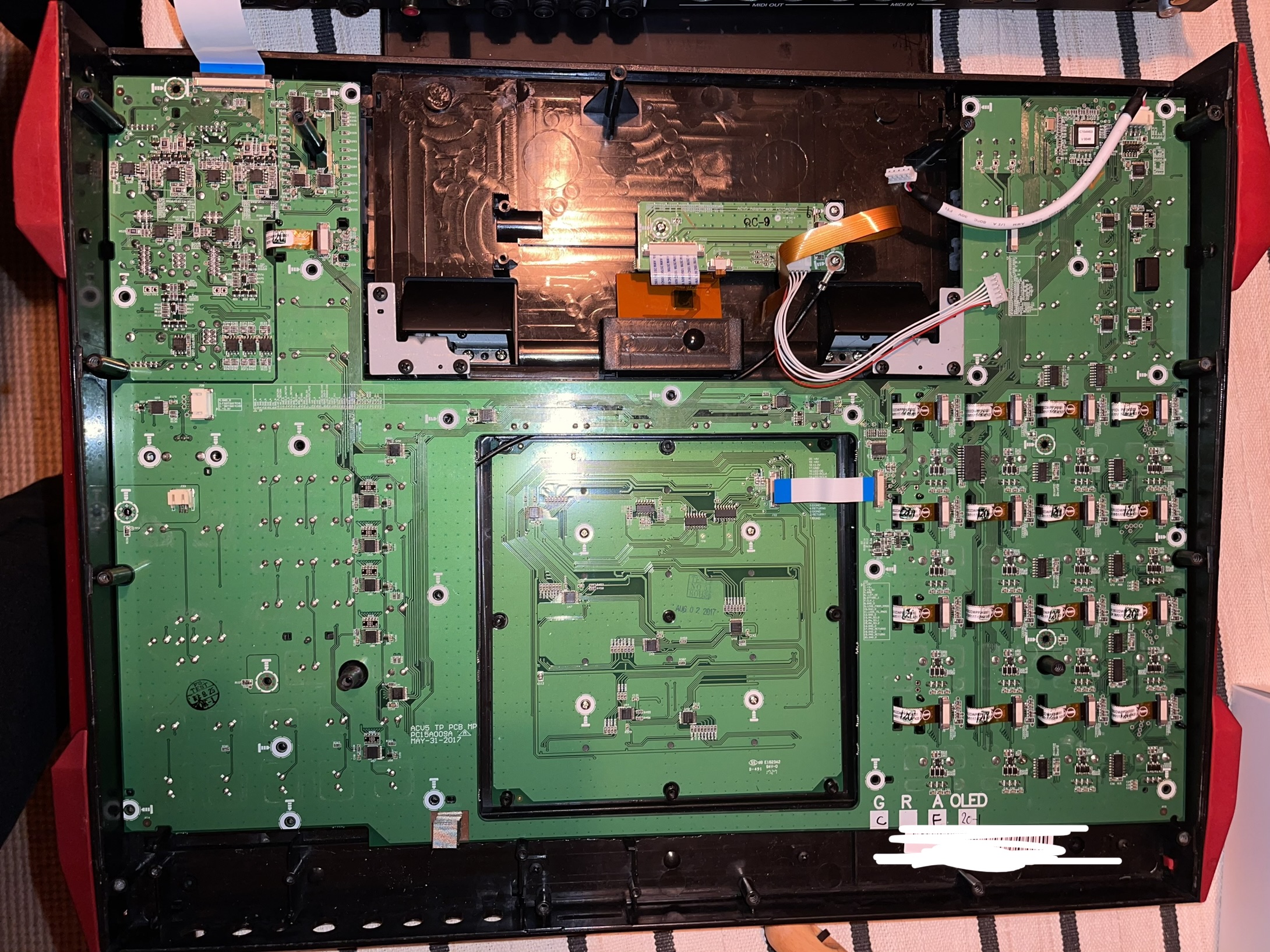
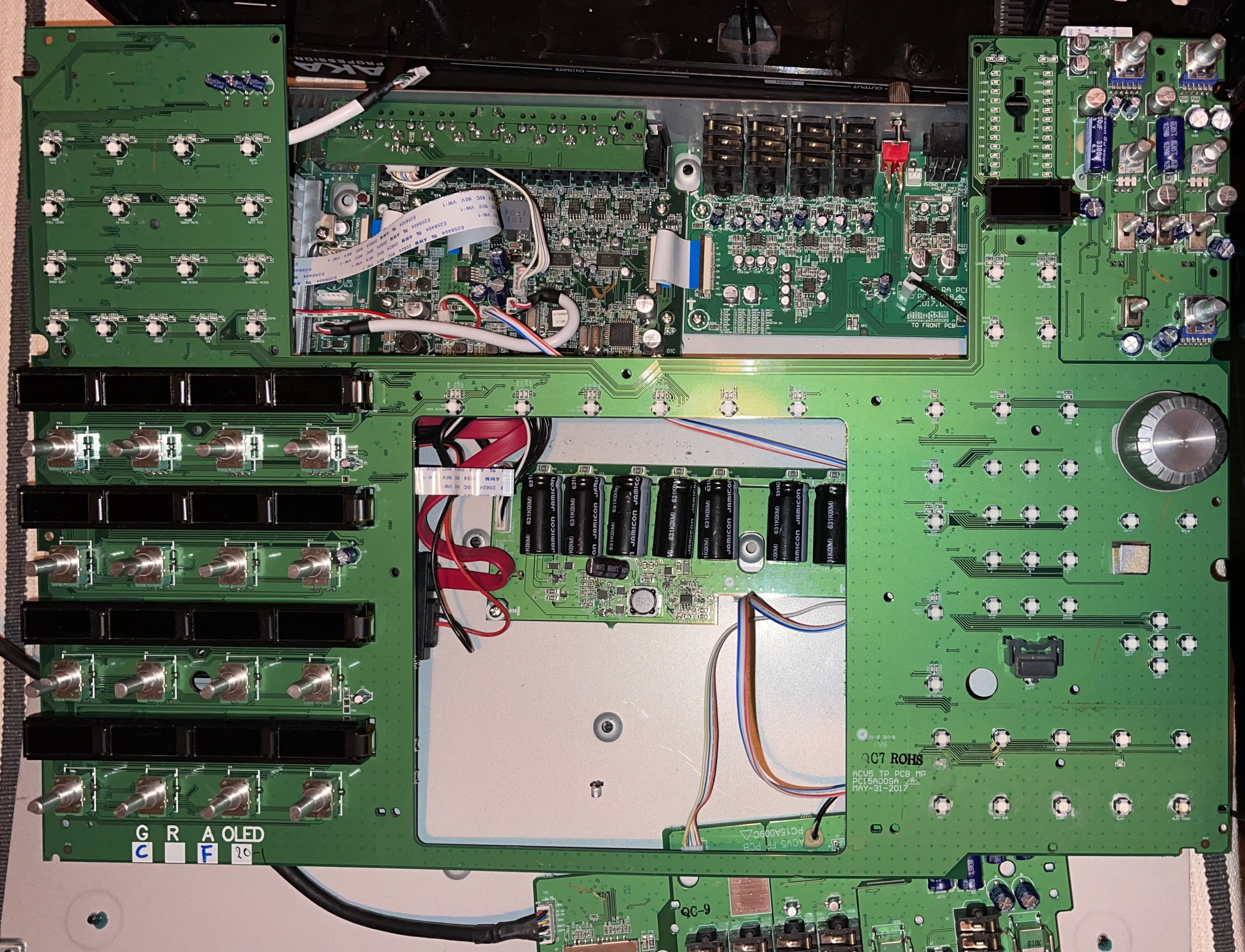
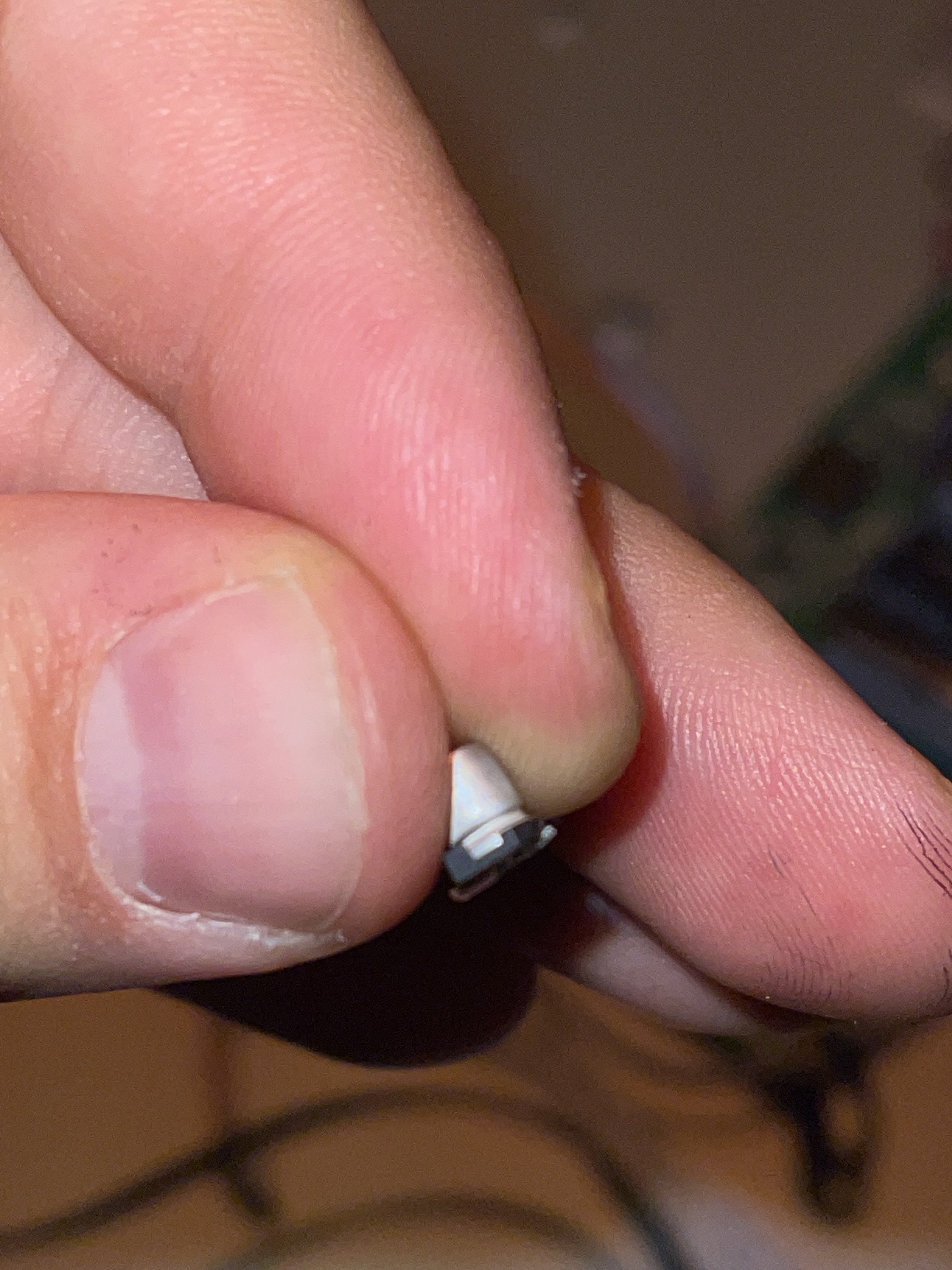
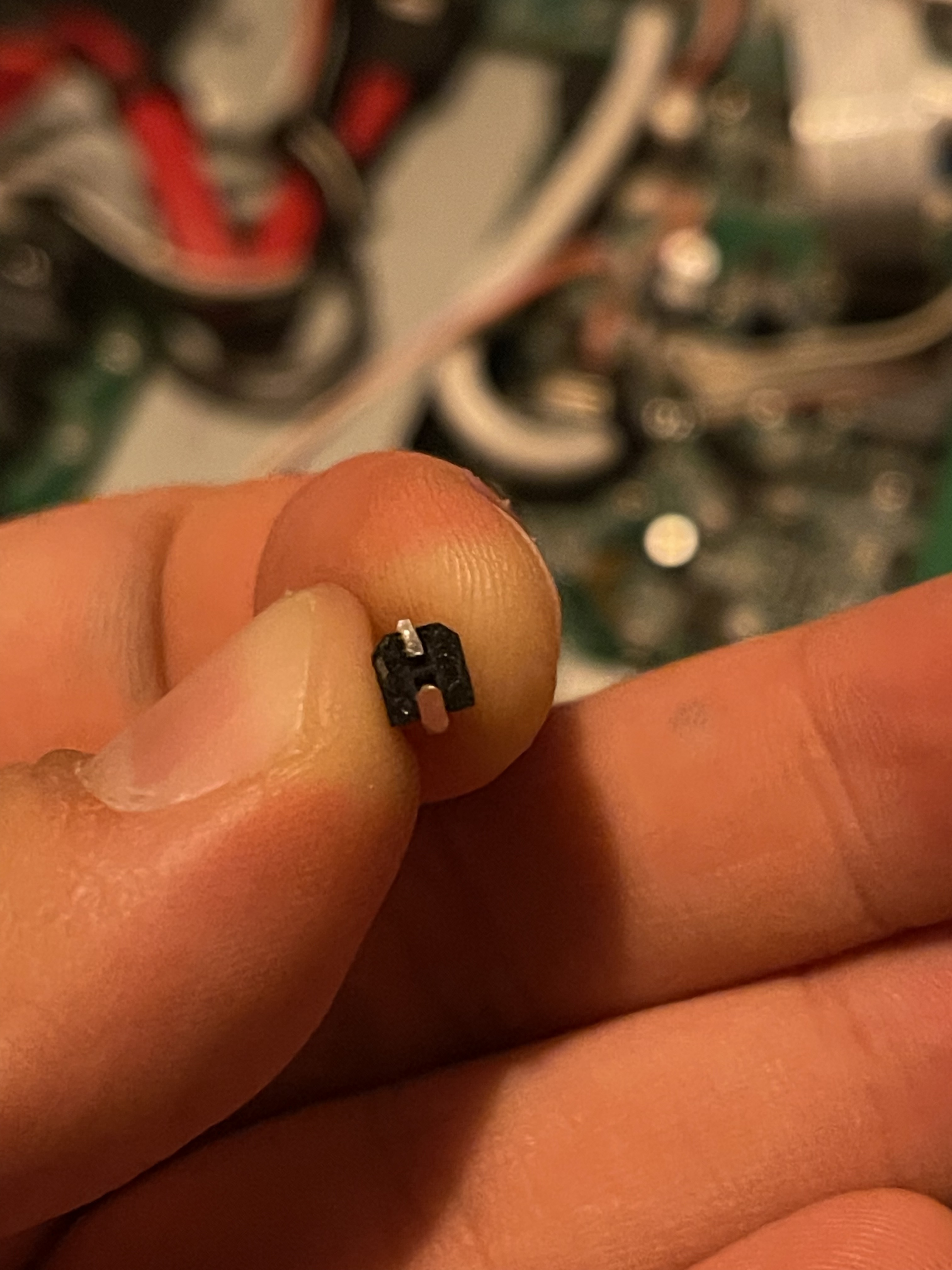
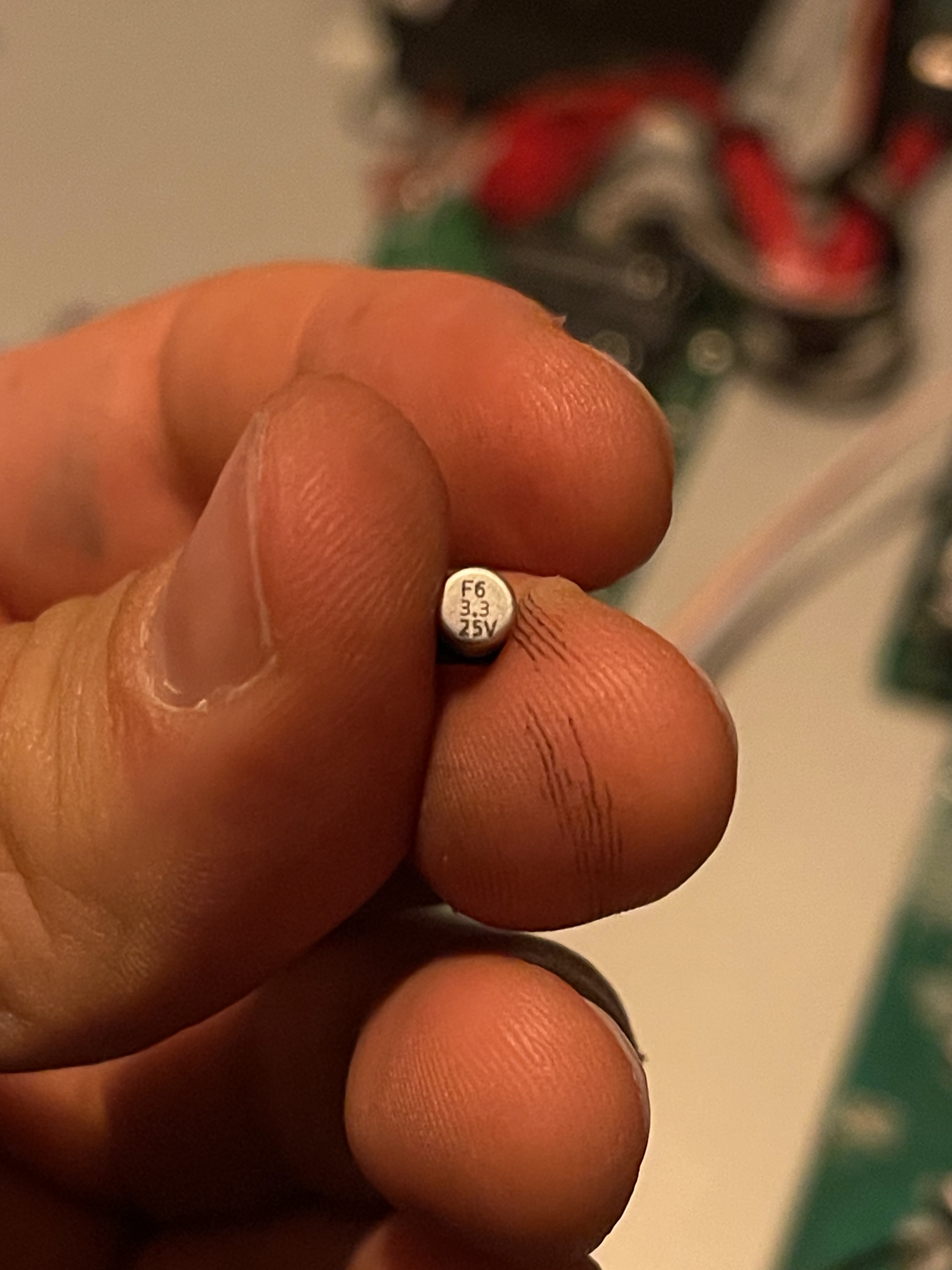
Opened the thing up again and took it apart pretty much completely, and low and behold I find a piece in the freaking case that seems to have broken off from one of the pcb boards.

Specifically it’s the pcb board that holds all the audio I/Os.

Here the photos of the piece (capacitator? transistor? whatdoIknow?) and the spot where I believe it should be:

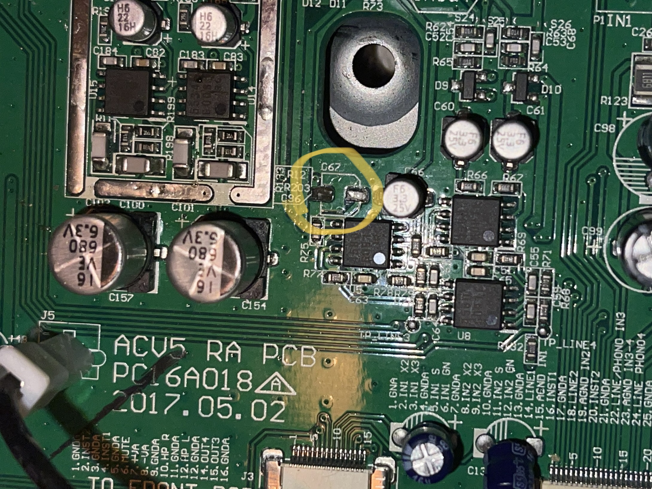
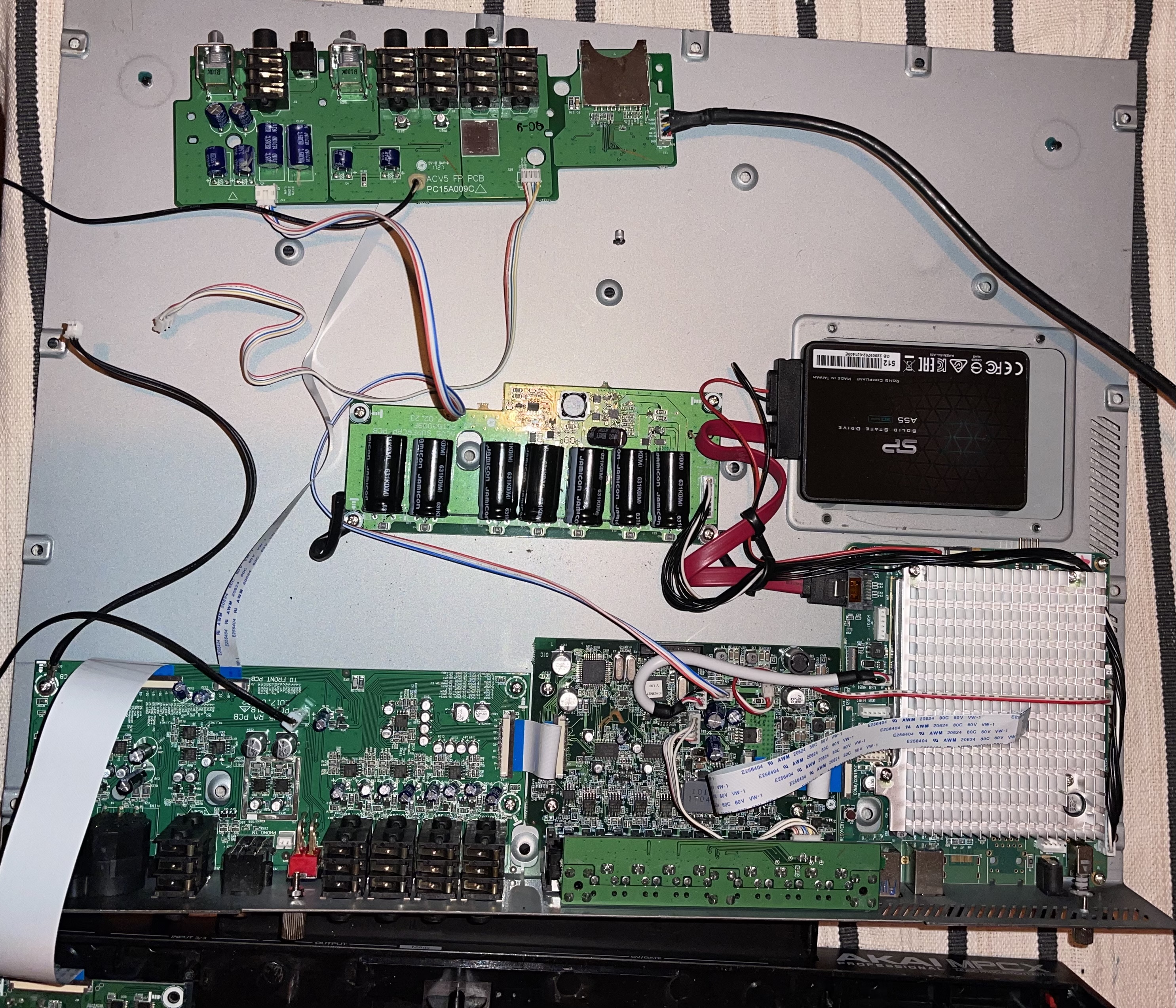
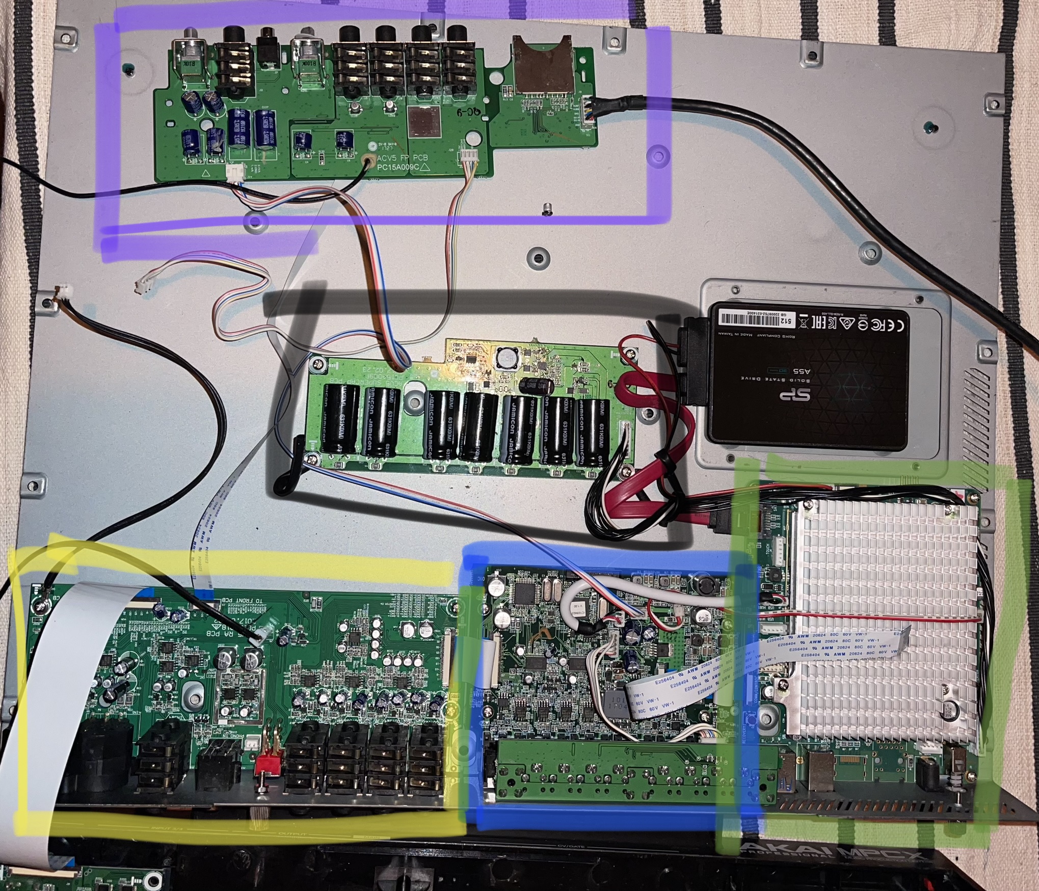
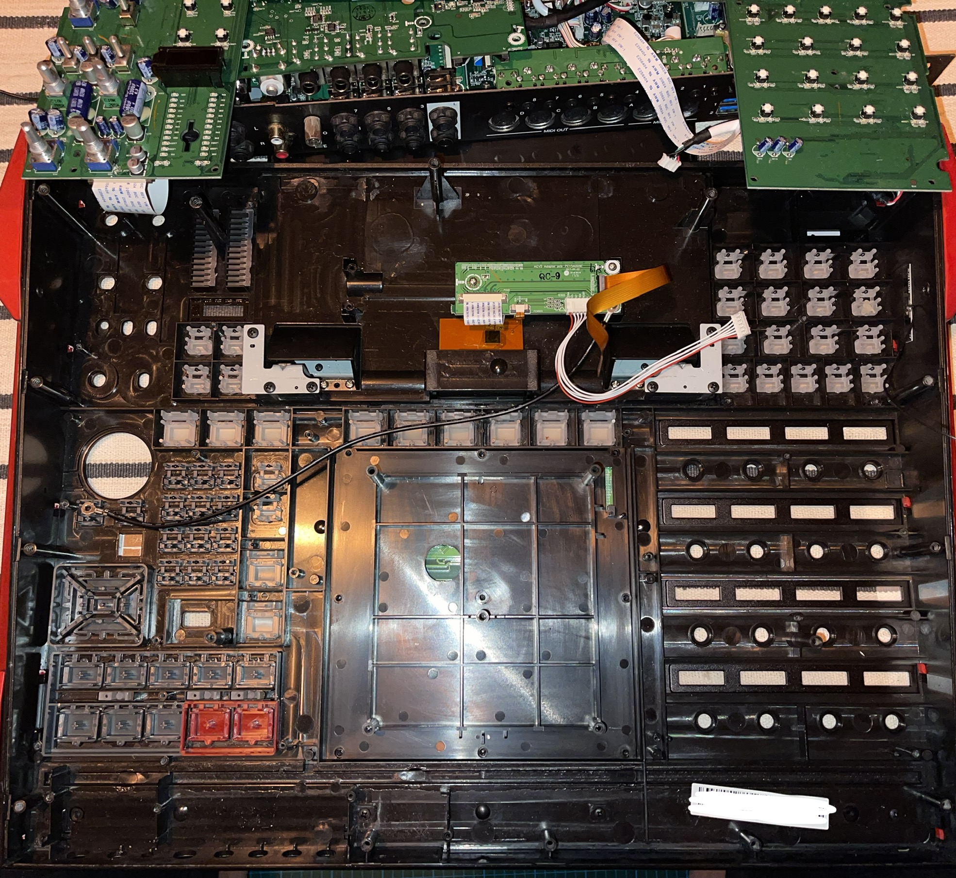
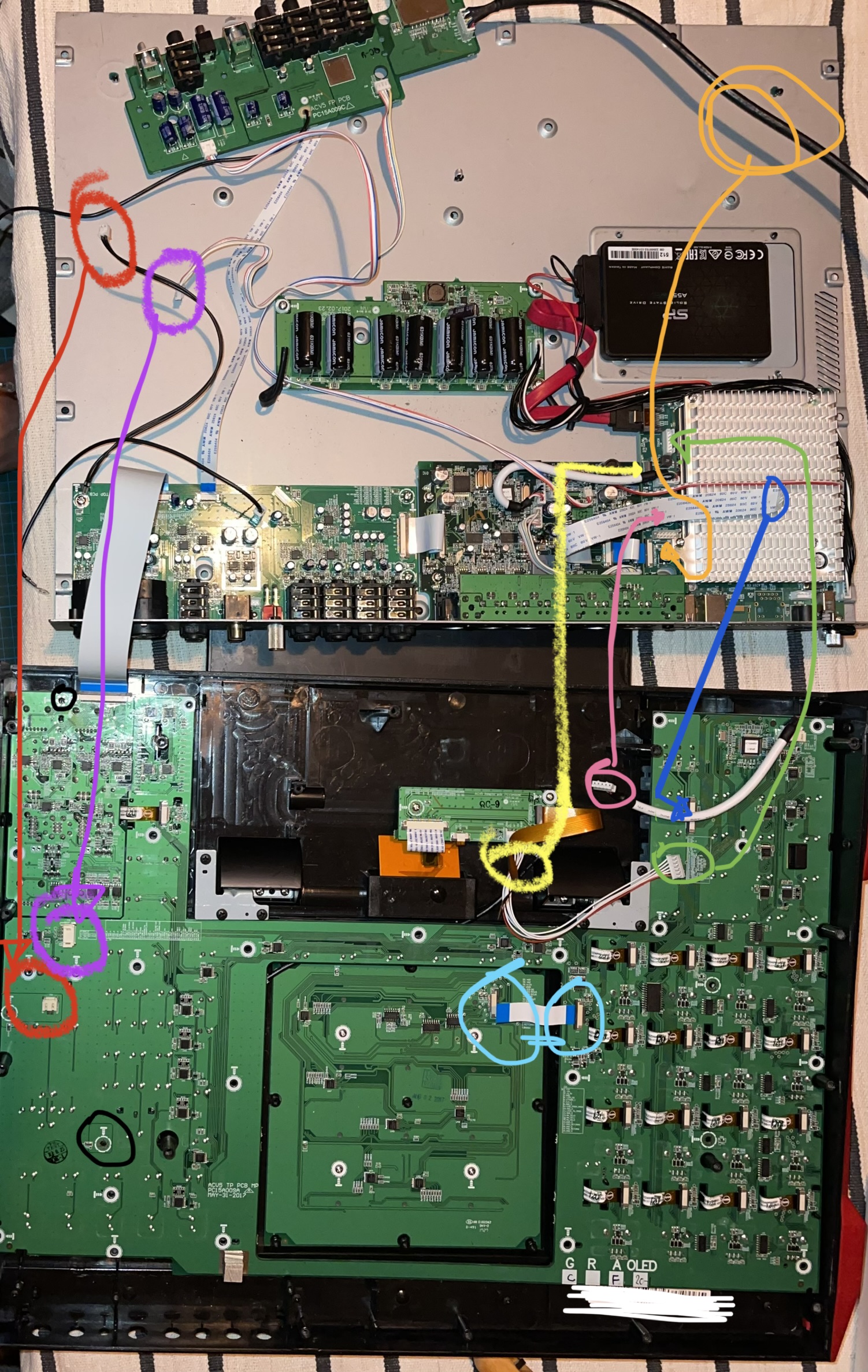
And here is the birdeye view of the disassembled MPC X and the affected pcb board’s position (audio I/O, marked in yellow…and for good measure I’ve highlighted the aforementioned flat connector in blue).

Since I have zero electric engineering/electronics knowledge, I wonder if those of you who do can give me your assessment:

A. What is the piece that’s “broken off”?
B. Is it indeed broken off or glued off etc?
C. Can it be fixed by reattaching it? (eg glue, soder etc)?
D. If the piece is busted, can it be replaced? (If so, then back to QC, ie how? :))
E. Am I right to assume that the thing isn’t working because of this piece or could eg the flat connector also still be an issue (ie bent/pins destroyed etc)? If the latter, can that sort of connector be fixed/replaced or are they purpose made for that particular pcb design? (I’m clueless, so forgive me if this question is dumb)

I appreciate any help/knowledge/recommendations those of you more knowledgable than me can share!

Cheers!

The part that came off is an electrolytic capacitor. It is likely replaceable, but it looks like the copper pad on the PCB might have come off with the cap, which makes fixing it much more difficult. It is hard to say how critical it is for functioning. In many cases these just provide stability, but they are definitely required in other cases.

3 Likes

Thank you for your response @warpigs330 — what do you suggest I do? Sounds like I won’t be able to fix it myself, correct?

Also, if anyone is interested: I couldn’t find any meaningful pictures of the internals, so I figure, while the patient is lying there, let take a few photos for those interested in how this thing looks on the inside. Here you go:

View of the PCBs mounted to the lid of the MPC X (minus the top piece, that one is mounted on top of the main controller PCB board when assembled — that one is headphone ins, footswitch ins, and SD card)

Here the same view again but with a whats what:

Purple - Headphone, Footswitch inputs, SD Card
Black - no idea lol
Yellow - Audio IOs (preamps, inputs, outputs)
Blue - Midi IO
Green - PC motherboard with the CPU, heatsink etc

This is the backside of the “main” PCB board (all the buttons and Q-Links are on the other side of it) which you’ll see first when you open your MPC X. The PCBs on the lid are connected by a bunch of connectors to this (four pin connectors and four flat connectors), which makes lifting the lid up and accessing the screws of this PCB board a propped pain. I’ve taken off the plastic piece that supports the pads in the middle, so you can see the back of the pads’ pcb board. Underneath that is the sensor sheet and the pads themselves (see the MPCStuff - how to change pads on the MPC X YouTube video for more details on this).

This is the “main” pcb board flipped over. It’s resting on the lid, so you can see some of the other pcb boards through the cutouts of this board…don’t let that confuse you :stuck_out_tongue:

And here the shitty plastic-y buttons that required me to go down this route in first place photographed from their ugly little behinds:

And finally a rudimentary attempt to document where the different connectors (between the different PCBs) attach to the boards.

Hope these are of interest/value for some of you.

2 Likes

A. What is the piece that’s “broken off”?
It is an electrolytic capacitor
B. Is it indeed broken off or glued off etc?
probably it still work, but they are cheap, you can think replacing with a new one
C. Can it be fixed by reattaching it? (eg glue, soder etc)?
D. If the piece is busted, can it be replaced? (If so, then back to QC, ie how? :))
Yes, if the copper pad has been damaged, probably the easiest way to repair is to solder the capacitor on the good pad, put some CA glue under the cap to fix it to the board, then scrap the solder resist off the track that was connected to the broken pad, use a thin copper wire to connect the capacitor pin to the track, that’s it. Solder flux is highly recommended.
E. Am I right to assume that the thing isn’t working because of this piece or could eg the flat connector also still be an issue (ie bent/pins destroyed etc)? If the latter, can that sort of connector be fixed/replaced or are they purpose made for that particular pcb design? (I’m clueless, so forgive me if this question is dumb)

The capacitor is on the audio board, so it’s very unlikely that it affects the display.
Try to reseat the flat cable, if it doesn’t work, you should check each track with a circuit continuity tester, look with high magnification loupe/microscope the two ends of the flat to check if the copper is damaged.

4 Likes

Take it to a phone repair shop. They do titchy smd stuff. Be pretty easy for them to do.

4 Likes

@DaGeek 🫶🏼🫶🏼🫶🏼 :star2::star2::star2:

@canister plenty of those around where I live, will check a few shops out over the weekend and see what they have to say

Thank you for taking the time to help!!!

1 Like

Did that just now and found that the cable has a tear at a bend close to one end of pins. So I think the cable is done. Would you know if such cables are typically based on standard sizes or will I need to source something proprietary to replace it?

Again, thank you so much for your help!

Connectors are probably standard, you can count the tracks and measure the distance between two tracks and total cable width, you will probably find a replacement on the internet, regarding the length hopefully you will find something slightly longer/shorter if not of the exact same length.
That seems the cable from the LCD controller to the LCD screen, if you can find some codes/part numbers you can use google to check for a direct replacement.

Edit: search for Flex cables/Flex LCD cables

2 Likes

Def an electrolytic capacitor that came off and it def looks like it ripped the tracer on the ground side. A phone tech should be able to get in there and replace some of the tracer or bridge it. As for the ribbon cable in question, are you talking about the white ones or the copper ones? Most parts can be found on mpcstuff.com or instrumentalparts.com. They grossly over charge for stuff tbh but you can also probably send them a pic of the thing ur looking for and they might help pin point the exact cable u need and look for that on mouser or digikey or the like.

2 Likes

Can you do a closeup pic of the damaged cable in question?

1 Like

Little update:

Thanks to your post @Schnork, I decided to look for a replacement flex cable for the LCD. Turns out they can be had on Ebay, 0.3 x 150mm 31pin LCD flex cable. Replaced the cable. For those who wanna know: on the LCD controller PCB (the one you look at when you open the box), the pins of the cable need to face DOWNWARD, on the main PC PCB (the one attached to the lid), the pins need to face DOWNWARD as well (assuming you‘re holding the lid open with all of the PCBs attached to it facing downward as well. So on that side, the cable needs to be inserted with the pins facing AWAY from the lid and towards the LCD controller PCB.

I‘m back up and running. Looks like my screen has got a little dead spot now, probably something fell onto it while it was stored away, really need to get more & better storage, but at this point I don’t care, I thought the patient was dead so I’ll take these little dings and dongs:


So far everything seems to work. Q-Links, buttons, loading/saving to the hard drive works, bluetooth, even the meter works again (it didn’t before I had taken the whole thing apart and reconnected everything).

No idea what that capacitator does that broke off on the audio interface PCB, will need to get that fixed still, but so far I‘ve tested audio out through the main outs and the headphone outs and those work, which is already great. Push come to shove I‘ll use the MPC with an external audio interface and just circumvent its internal interface till I can get it fixed. Will test inputs later on tonight.

Big thanks to those of you who took the time to comment & help (@warpigs330 @DaGeek @canister @orion @Schnork), I very much appreciate your support and without your contributions I would have just given up on this…instead I got it working again (basics at least :)) and I learned a few things about electronics, flex cables, their connectors and the MPC X‘s internals :slight_smile:

8 Likes

It’s fairly likely that the capacitor is just a bypass/decoupling capacitor, which aren’t essential for the device to work, but make sure it works normally with variations in power draw, and just generally provide stability. (Basically acting like a really tiny battery so if the chips need extra juice for a nanosecond they can get it from those caps)

3 Likes

Looks like you‘re right. All inputs seem to be working flawlessly, phantom power works as well on both mic preamps, the only input I haven‘t tried yet is the RCA one.

My Rec Arm, Read / Write, and Solo buttons underneath the meter as well as the screen underneath the meter don‘t seem to be working correction: those work as well, was a matter of settings in the Preferences tab.

everything works just fine.
:relieved:

7 Likes