I’m looking for folks with some electronics/firmware knowledge. I have an Endorphins Cockpit 1U that has a firmware update. It addresses an issue with mode 3 of the sidechain algorithm. I desperately want to do this firmware update but the method is definitely not something the average person should be doing. As per the README:
"UPDATE PROCEDURE:
For that update you will need to flash the firmware via ST-LINK V2 programmer using STM32Cubeprobrammer from your Windows computer.
SWD cable pinout:
| [O] (O) (O) (O)
3.3V-GND-SWIO-SWCLK
(square hole with the line on the side corresponds to 3.3v)"
I’ve emailed support twice and I’ve not received a response. The last time was only a couple of days ago but neither time did a receive a confirmation email. So, I’m asking here.
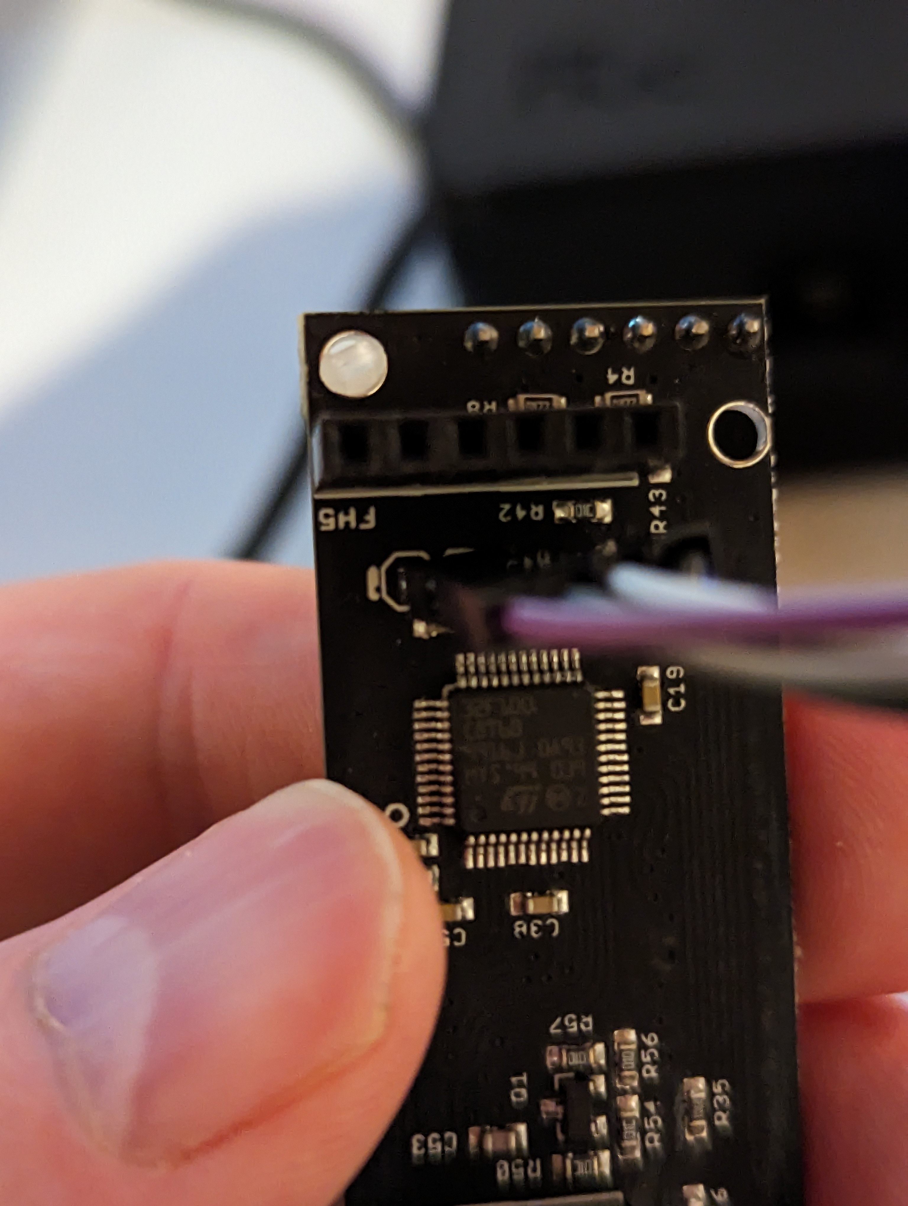
I first purchased an ST-Link v2 Programmer. It’s just a USB stick type that came with 4x Dupont female-to-female wires. The README file says absolutely nothing about where these should connect. After removing the two boards that attach to the main part of the module, I did find the ST32 chip and 4-holes in the board. The diagram above now makes a lot more sense. Because these are just holes in the board and not a female header, I assumed that I needed female-to-male Dupont wires. I’ve acquired those.
So, I connect the ST-Link to the board with the holes and the STM32 chip on it. The male pins don’t seat snuggly into the holes. That’s issue one. Issue two is when I load up STM32CubeProgrammer, the ST-Link is detected but the chip isn’t. Now, I don’t know if the board needs euro rack power or not. I figured I’d try it with just the ST-Link first to see if the 3.3V was all that was required to connect to the chip.
I don’t even know how I would connect euro rack power to the board as it’s on another board that snaps into it. With that board attached, I’d have a hard time putting the male end of the Dupont wires into it.
I’m just lost with this stuff. I wish the vendor would’ve been a bit more specific with the instructions. It’s not something that an end-user should just know.
If anyone can assist or provide some insight, it would be greatly appreciated.
I assume they mean the manufacturer of the microcontroller, not the manufacturer you’ve been trying to contact.
I really don’t know my head from my ass when it comes to issues with microcontrollers, but I am a master of the google arts, and I found a thread from all about circuits where it implied the ST link can’t be used when the STM32 is powered with 3.3v, meaning that 5v is required.
You could consider a buck converter maybe? Something to step the power up from 3.3V to 5V? I don’t know if that would apply here, one would think there’s a better way if this is the required method to update firmware. Check that thread out and see if you can glean anything else useful, I didn’t review it too carefully. Good luck, super frustrating I’m sure, hope that at least helps to confirm what you were thinking.
If this is a Eurorack device, then it’s not one which is being provided with 5v directly, it has the 10 pin Header which means only +/- 12 (unless another header is also used) so somewhere on the board there must be some step down circuitry - failing any clarity from research, you could look at the board for potential clues about how the voltage is stepped down to get some assurance that 5v is (potentially) the way to go
Ah indeed it does say 3.3v in the specs cut’n’pasted , my bad, just a thought
Maybe it’s best to solder the (or some other) cables to the pcb and leave the female headers at the back for attachment to the USB device - if reach can be arranged - therefore the item can be independently active (if required)
If it were my module and out of warranty I’d solder a 4-pin male header to the programming connection on the module rather than stuffing pins into its holes.
I’ve done this twice and received no response. That text file is literally all the instructions they provide. It is far too vague for a layman to understand. I was able to figure out most of what’s needed but the Dupont wires clearly don’t seat properly into those holes on the board. I agree that a header of some sort is required.
The module is definitely still under warranty and I’ve never soldered in my life so that’s out of the question.
I don’t think Endorphines ever intended for the module to be updated hence the lack of a USB port or proper header to connect to. They just didn’t realize that the attack was too fast on one of the sidechain algorithms. It’s definitley something I want fixed as it’s the algorithm that lets you dial in the SC depth per channel instead of having the same depth across the module.
I’m wondering if there’s some type of cable with larger male pins in on end and separated female ends on the other?
Failing that, are 4-pin headers easy to source? Is the spacing standard in that it just needs to drop into those holes and be soldered on from the other side? I’m sure that solder job falls under the ‘dead simple’ category.
I remember flashing the same type of chip for a firmware change on a floppy drive emulator. The pin header on the device didn’t match any of the instructions and was barely labelled. It was definitely a head scratching and nerve wracking thing to do as an early electronics dabbler so I can completely sympathise with where you’re at.
A quick solder of the cables to those holes is pretty straightforward, but practice a bit first and have a multimeter handy so you can check you haven’t blobbed too much on and joined two wires together by accident. If you don’t have these then some kind of header is a better bet if it doesn’t need soldering.
In the spirit of bodge I would also be tempted to strip a small amount of cable from each of the wires and see if i could wedge it in each hole with a toothpick. Again you’d want to have a multimeter to make sure you’ve got a connection and you would have to be super careful not to bump it. In fact, definitely don’t do this (but I’d probably try it).