TL;DR I put 3 x 18650 lithium ion batteries and some electronics in a Digitakt to make it ultra portable. Gallery here: https://imgur.com/a/muZwgLX
I like to bring my Digitakt downstairs and just fiddle with it on my lap in the evenings. This isn’t ideal since it requires 12V. Using a 12V USB-C to barrel jack cord and a battery works, but it’s still some extra junk you have to cart around. I wanted it to be totally self contained. After finding some photos of the internals I saw there’s a huge empty cavity in there. The hard part was going to be figuring out how to convert the variable voltage coming out of the battery pack (ranges from 12.6V when full to ~8V when empty) into a steady 12V.
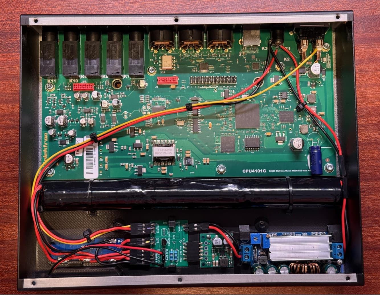
After some research I went with a 12V step-up/step-down voltage regulator. That gets 12V from the battery pack to the Digitakt itself, but then I need to recharge the battery. I found an adjustable buck/boost converter that lets you dial in both the max current and max voltage, perfect for charging a battery pack like this. Then I needed some way to protect the batteries to make sure they didn’t over/under charge. This BMS board handles that job. Then I wanted a way to indicate the current battery state, and not just wait for the Digitakt to turn off when the battery got too low. This display does the trick, you just need to press a button to turn it on for a few seconds. The only downside to this combination of items was that the 12V voltage regulator draws about 0.03A continuously, even when the Digitakt is off. But, there is a way to put it to sleep which brings the amp draw down to practically zero. To do that, I designed a small circuit board with a transistor and a couple of resistors. It also acts as distribution center for all the various connections.
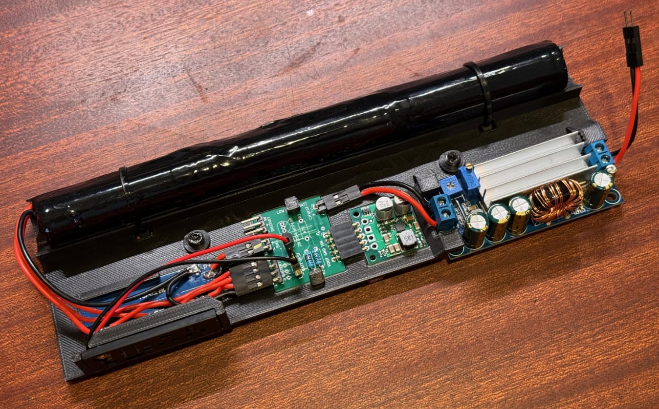
I designed and 3D printed a bracket to hold all of the components, and using the VESA mount holes on the bottom to secure it. The little blue squares in the photo above are thermal pads so that any heat is spread out on the bottom of the case. To connect everything to the Digitakt mainboard I cut the lead that went from the + of the barrel jack connector to the mainboard. I wired the input of the buck/boost to the barrel jack. I connected the output of the 12V step-up/step-down converter back to the mainboard. Then I ran a wire (the yellow one) from the power switch to my custom circuit board to enable sleep mode. When the power switch is off, the 12V regulator is asleep, and when the switch is on the regulator wakes up and sends 12V to the mainboard. I drilled 6 holes in the front so I could activate the battery level board and see the LEDs.
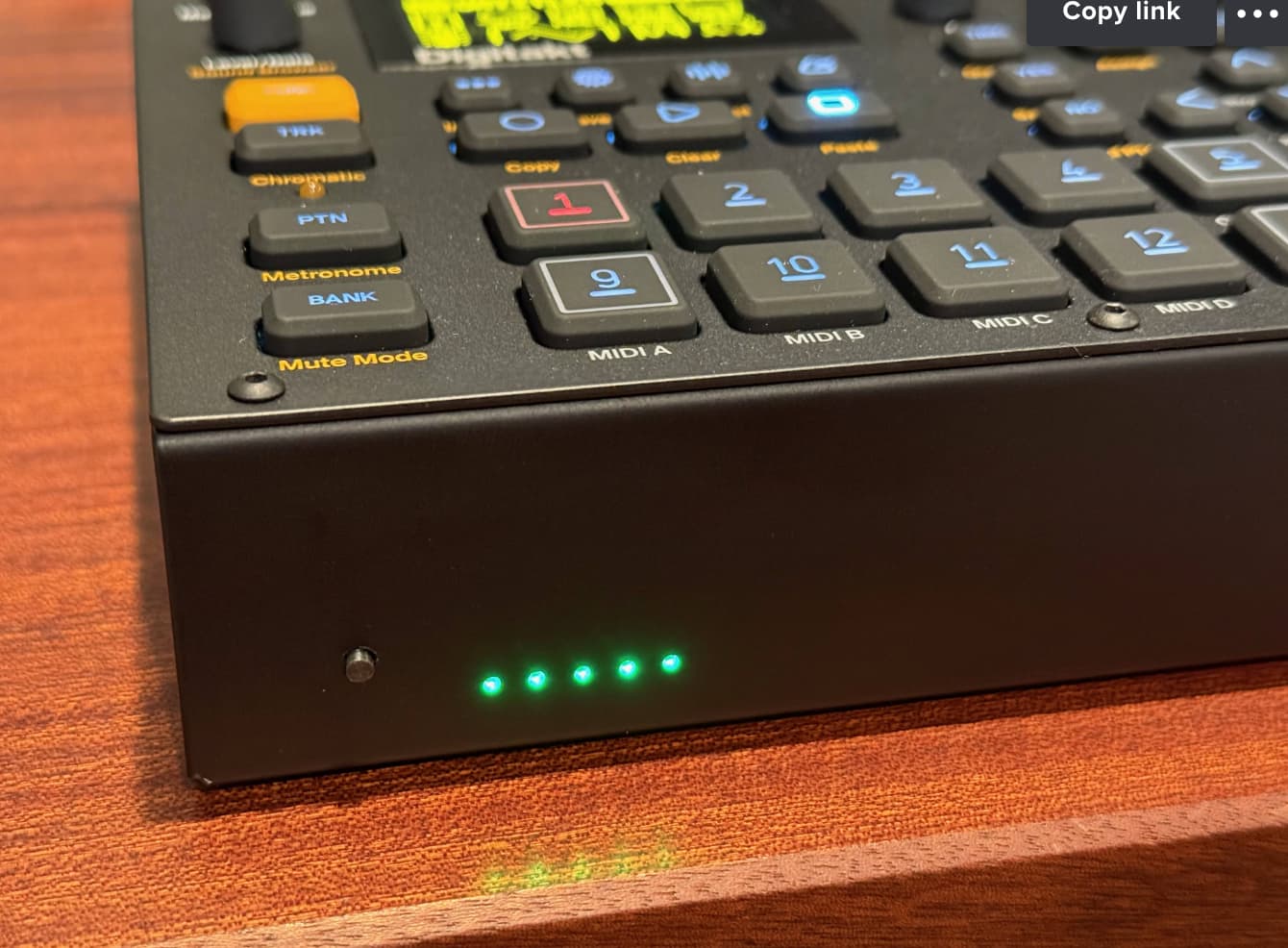
And it works great! I get around 7 hours of usage, and then it recharges in around 3 hours. I use a bluetooth audio adapter to send the sound to my Airpods Pro and I’m 100% wireless!
Comparison to Other Solutions
I discovered the big battery powered thread and noticed some differences between that one and mine, mainly that it connects directly to the stock 12V power input, not cutting the lead between the port and the mainboard. The side effect of this is that the 12V jack will now send power OUT as well as accept power in. That seems a little dangerous to me as you would normally never, ever expect an input power jack to be sending power out.
They also rely on the fact that, as the battery drains, it eventually crosses a low voltage threshold (around 10.8V) where the Digitakt can’t run any more, and shuts off. I wanted to give the Digitakt the exact 12V it’s designed for the entire time, for as long as the battery’s BMS is willing to provide power, which is down to around 8.9V on my model. With the step up/down converter I’ve got, no matter where the battery is in its voltage range, the Digitakt gets the same, steady 12V.
With the setup in that thread, the battery never gets 100% full (12.6V) because the stock power brick will only supply about 12.1V max. On mine I’ve got the adjustable buck/boost that gets the battery right up to its max 12.6V.
The setup in that thread is much simpler than mine, and if I had found it before I made mine I probably would have done the same thing! But now that I’ve found it I’m glad that my more complex/expensive setup actually has a few benefits, and that I didn’t go through that extra work for nothing. ![]()