Diy power distribution board

Hi there,

I would like to build a power distribution board for some 12v, 9v and 5v devices in a box. I’ve tried running almost everything with splitter cables and it works well. But it seems that I have a many different cables and it could pose as a mess. I was thinking of diy-ing a power distribution box that house a 12v input split into 6 12V dc jacks and 2 of which will go to one 9v power block and one 5v power block, then the 9v output will return to the board and be split again into 5 or 6 dc jacks.
I didn’t find any schematics online but I think it relatively simple just 1 input which will split to the dc plugs.
I was also wondering if I should add a diode before the output of the dc plug? Can anyone advice me on this?

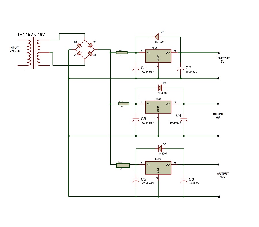
for your need you should have regulators for each rail (5V, 9V, 12V) and some filter capacitors surrounding them (look at the recommendations in their datasheets). these regulators are called 7805, 7809 and 7812. beware of the different pin orientation for these regulators.

here’s an example PSU schematic. ignore the transformer+rectifier diodes+fuses - this is where you plug your 12VDC in.

good practice is to have a diode reverse biased across these for reverse polarity protection so they don’t get damaged in the case where input is shorted to 0V. for reverse polarity protecting the rest of the circuit you should place another diode across the supply and 0V.

also see this great ±12V wall wart PSU tutorial from MFOS:

also, make sure your devices does not draw more current that your power supply can supply, assuming you are powering this circuit off of a single 12V DC/DC wall wart.

after this you can simply solder dc plugs across your rails as needed.

Thanks for the reply htorju!!!

I’m actually using a 12V/10A power supply block and these,

I chose 1n4001 for 1A outputs and 1N4148 for 300ma outputs which should be more than enough for my 9v devices.
I’ve made a rough sketch on how I think I should add this. Is this right?

I have 5 devices (DT, DN, Pulse2, Blofeld & MB33) on 12v, 5/6 devices on 9v and 1 device on 5v.
The 9v blocks proves maximum 2A and the 5V block gives max 4A. So 12v devices have remaining 4A. Yes I calculated around 1A for each of the 12v devices, but actually the waldorfs n MB33 needs lesser. So far I’ve test this setup with wire splitters and only with DT, DN, pulse2, 3 pedals, a small 9V mixer and a RPi and it works fine. only that I have to startup the DT and the DN last, otherwise it will reboot. Still haven’t acquired the blofeld and the MB33 yet, but I think it should work less than 1A.

What are you trying to achieve by creating this power distribution system?

I’m only asking because there might be more versatile solutions depending on the purpose behind it.

because what I’ve used till now are splitter cables of 1 input and multiple outs. there are 2 such bundles of 3 splitters and 8 splitters in the box and they still need to run to the devices themselves. so with a ‘central’ output source, i would reduce the need for the splitter cables n just run individual cables out to the devices. that was the idea, reduce too much cables.

what other solutions would you offer?

Well it just seems like you’ll be putting a lot of work in for building a specific set of supplies for a specific set of gear.

If your gear changes down the road then you may have to change your power supply distribution box as well. Not enough current output, different voltages like 9V A/C (odd one but it’s out there). Some gear has center negative, some has center positive etc…

If your purpose is to reduce the amount of cables you could build a distribution box that simply holds your power supply boxes that came with your gear.

Inside you have female DC ports to plug those original boxes into.

From there you route female DC jacks to female DC jacks up on your desk where your gear is. Space them out around the desk. Then you plug on whatever original power supplies you need and hide the power bricks in your “distribution box”.

The use DC barrel to DC barrel connectors to plug-in you equipment from the corresponding DC jacks on your desk.

I mulled this for a long time and considered a main power supply box and instead went for the modular power brick distribution idea when I built my desks.

I did power, audio, usb, and MIDI but you could just do power.

The only catch is having both 2.1mm and 2.5mm barrel jacks. I use 2.5mm for the female barrel connectors and then use either 2.1mm or 2.5mm from the jack to the device as needed. All of my gear works this way so far with no problems.

It’s easy to fish out the power supplies when needed.

There’s nothing wrong with your solution but it might be extra work and more money down the road.

I also know this is very different from the road you’ve already started down. It’s more food for thought on the whole concept really. A different way of approaching a similar outcome.
ah, sorry. i thought you were building a power supply for a DIY circuit or synth requiring different voltage rails…

i agree with this. i would personally not build a new supply for larger gear you bought already unless you have a very good reason. if you want an easy portable solution for your gear the best thing is just a switched power strip with every supply that came with the gear plugged in. sounds like your goal is to have a pedal-style/daisy-chain/splitter power distribution for everything but i wouldn’t do that for anything else than pedals.

1 Like

your setup looks great! But my purpose is to house all the stuff into a portable box, hence the distribution box and wanting to minimize too many cables inside the box.

Generally I just want a single Ac power cable to wall wart to power up all the devices.

I learnt the hard way trying a pedal-style/daisy-chain/splitter power distribution for the elektrons and it crashed the DT, so I learnt that from experience. Generally I’m not going to run any pedal style daisy chain pattern for any o the pedals to prevent noise in the signal.

Generally I’m going down the road of minimizing my gear to just these and try to make the most out of it.

1 Like

just referring to the power distribution diagram above, do you think this is the way I should make the distribution? with the diode before the dc output ?

Those diodes in your diagram are signal diodes . If you’re looking to protect your power circuits from your music equipment (which I don’t think you need to do) you’d want to use zener diodes instead.

Protection diodes are generally on the device to protect it from an external power supply. The other way around isn’t usually necessary.

1 Like

ok. thanks for the note and advices! greatly appreciated!

1 Like

there are better ways to save space. bringing less gear for example.

not really recommended. how much current do you expect to draw in total? also, you have listed one device which do not operate on DC power. be careful.

you nearly bricked your digitakt by daisy chaining it and now you want to build an aggregate PSU for all your devices? designing a PSU for multiple devices isn’t as simple as adding together currents written above the power sockets and hoping for the best. by having separate PSU’s each device is electrically isolated from each other. by having a single PSU you introduce the possibility of noise and bleed across the devices and you risk underpowering your devices. in the worst case you risk destroying your device(s).

is it worth it? don’t do it!

1 Like

I agree that it’s actually much more complicated than it seems on the surface.

You’re essentially placing all of your devices in parallel and relying on your regulators powering each device to maintain their DC voltage.

Each device is trying to drop its voltage on all of the other devices which are also in parallel. You should still have a strong grasp of what’s happening with interactions of voltages so you can plan for all possibilities.

At least know Ohm’s law (the most basic foundation of all electronics). Also know what happens with voltages when you place various components and/or entire circuits in parallel and series with each other.

I’m not one to stop someone from experimenting but make sure to do your research if you want it to be reliable and safe for your gear.

I recommend finding example schematics of the exact type of circuits you’re trying to make and modifying them to your needs.

Good luck to you.

yes I almost cried after the elektron shutdown by itself when I did that. But luckily after switching back to the normal power supply it worked again. so lesson learnt! never again.

anyway, just want to share this, I went from using these… with female connecting plugs to the devices

to making this

Now I lose all the female plugs and just use dc to dc plugs and there are no more lose connections. And now when I start up the pulse2 after the Elektrons, the Elektrons will not reboot itself. Great! Maybe there was a loose connection somewhere that cause that.

I started by testing 1 output for the 12v supply on the left to the 9v supply on the right. and it works, so I finished soldering up all the dc outputs. I skipped the diodes as I started to think that what i actually needed was something like a power strip that all output the appropriate voltages.
Tested with all the gear that will use this yesterday and it works great!

now waiting for the enclosure to arrive so that I can install everything.
anyway. thanks for the tips!

1 Like