Usually, capacitive touch chips are sensitive enough to detect touch even through 1-2mm of PLA / PETG. I guess, you could hide the foil under a panel, if you wish.
1 Like
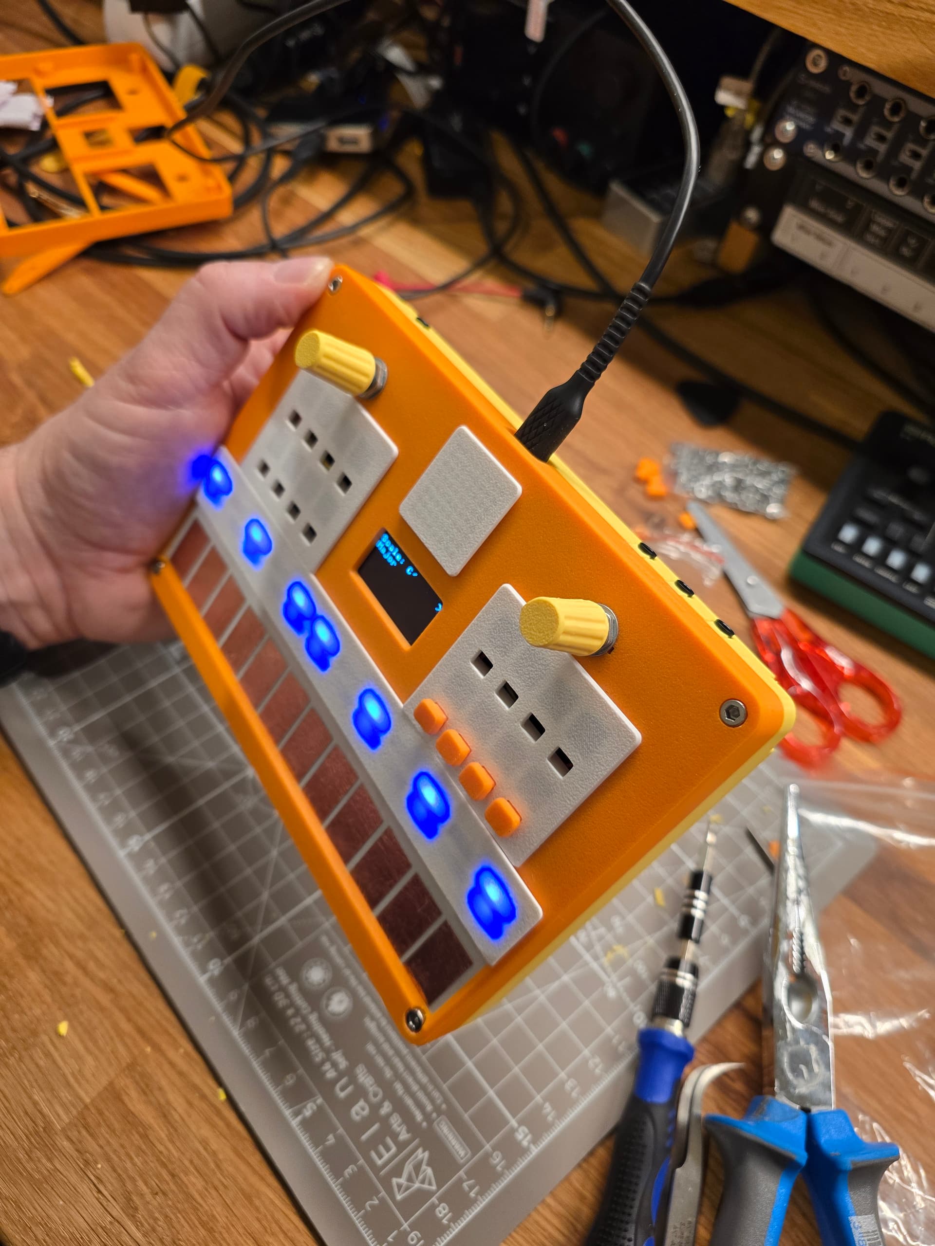
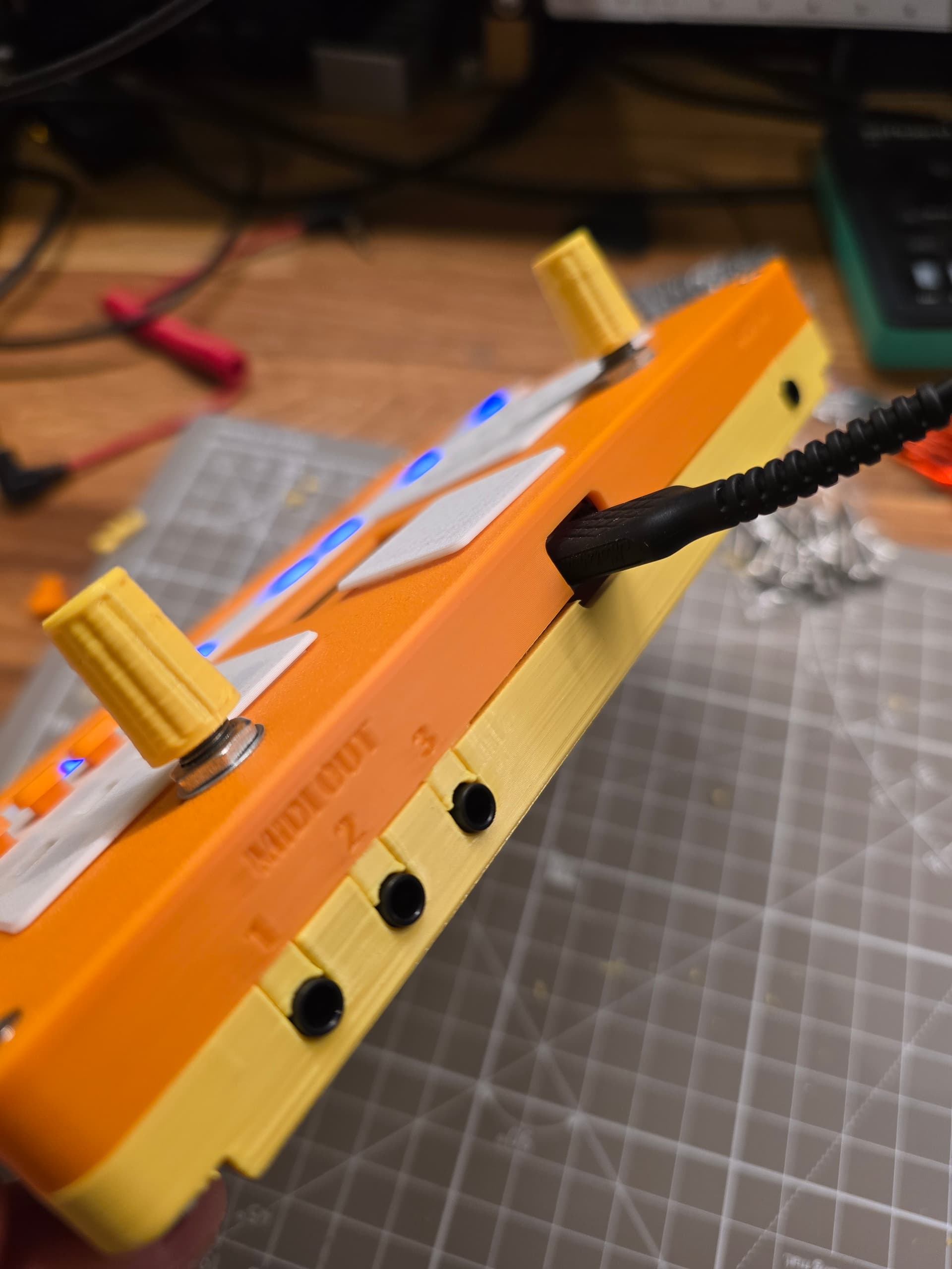
Today I could finally put (almost) everything together. The last 3D parts were printed on my A1 mini and I could start assembling. Well, it didn’t go as smoothly as hope - I should have expected nothing less, to be honest. In the end, I had to improvise. I forgo - lazy me - to add a screw in the 3D drawing, so I had no room for it inside the case in reality. I used a box cutter to make space; it is not nice, but it is on the inside, and I already made a to-do to fix it in 3D for future prints.
I am really excited that somehow everything really fits inside this box and that it still works ![]()
I mean, to be honest, the wire management is unfortunately a mess. Probably a fundamental design issue because my beloved 30AWG silicon wires are pure chaos, and it is really hard to get everything assembled without getting the wires in between stuff.
Anyway, it’s a prototype, it’s my first larger electronics project, so I am happy to have things to improve and learn.
The only missing parts are 12 buttons. I forgot to print them, so this will be done next, and then I’ll focus on the software. I really hope that ESP32 Wi-Fi still works through the case and next to the other electronic components, as I really want to play with loading chord progressions from online chord databases.
If you are still here, thanks for reading; it is fun sharing the progress.
Thx @shigginpit for breaking the string
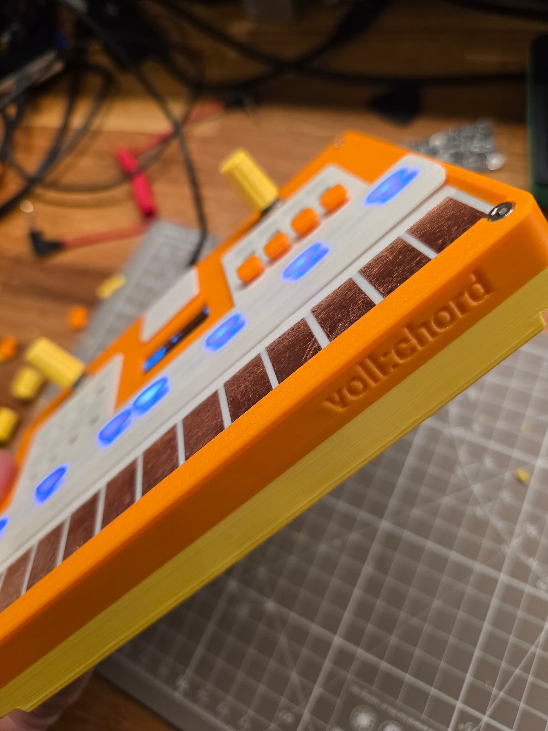
@diswest Thank you for the tip. I read that already and I originally designed it to have the sensor pads inside the device but I like the look of the copper foil touchpads so much that I put them on top and just added transparent tape to make it more robust but preserve the look.
8 Likes
No worries, keep up the good work. I bought a Tubbutec MIDI retrofit for my SH-101 but got cold feet about modifying it so I might put off making that decision and make time for finishing something else instead.
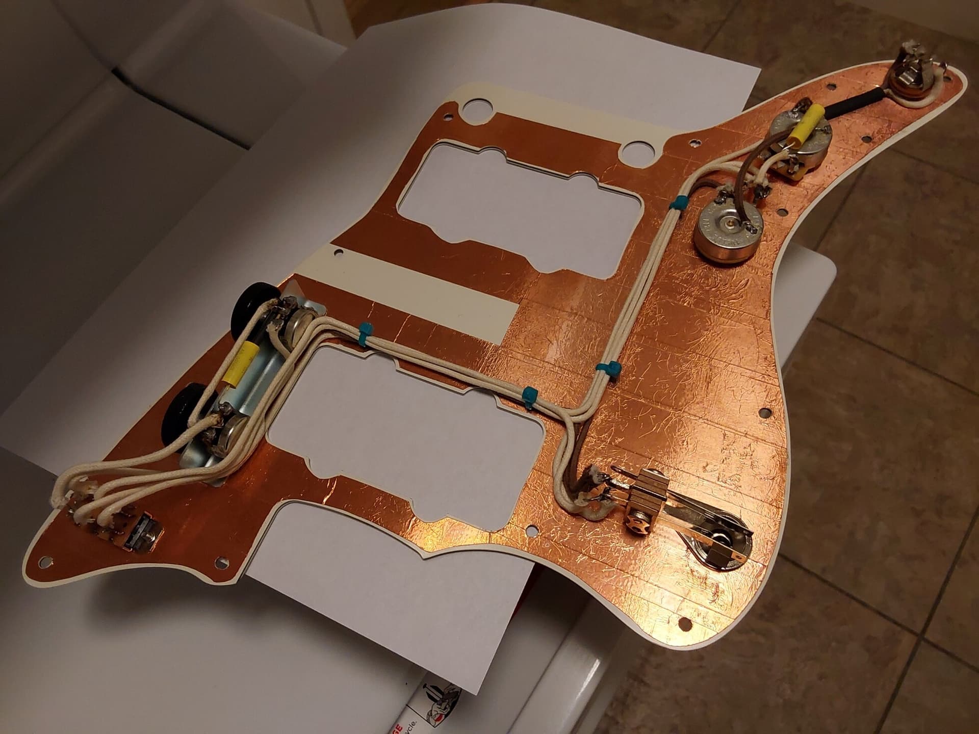
I have a jazzmaster which is about 90% done at this point which I built this harness for and it came out pretty well so I’ll likely finish the guitar up first.
Certainly not as cool as a MIDI chord machine though.
8 Likes
I have limited experience with the esp32 but the wifi has always been strong enough for the stuff I’ve done with them, certainly better that the BLE implementation if consumption is a factor. When researching them before getting any i planned to try some antenna mods but i never got around to it.
2 Likes
More copper → more shine → more coolness!
2 Likes
Wow, that’s some tidy cable management on the Jazzmaster! Looking forward to seeing pics of your upcoming projects. Every DIY electronics project is exciting to me, so keep the pics coming!
@blurrghost cool, thank you - fingers crossed! I’ll test it soon. I’ve seen some antenna mods and boards with an external antenna plug, but that’s for another time/project.
1 Like
Oh yeah, I’m sure there are plenty of known mods, that dev board platform is really well documented. I think i even have one or two still in the package with the little micro sma type connectors (bought a box of assorted esp32 boards about a year ago). I do want to play around with that eventually as the transceiving properties are of particular interest to me and I’ve done a bit of rf work in the past, antennas are fun but a deep rabbit hole all their own. Funny enough i never even thought to use these for audio projects even though the majority of my electronics experience has been audio-centric.
1 Like
And since I’m in this thread already, today’s electronics project was fixing my casio sk1. I’ve had many, this one i picked up at a thrift shop a couple years ago for two or three bucks. The sampling never worked but it was still a great board. I replaced a broken input jack and the sampling works now. Must have been causing a short that made it “detect” a cable thereby defeating the mic. Cleaned up the insides while i had it open, removed the old foam, etc. I also found a dozen or so staples inside, luckily all stuck to the speaker magnet. Not much of a project, just killing time while some foam hardened in my frigid shop.
3 Likes
started a new project yesterday, a capacitive touch keyboard, possibly with poly-aftertouch.
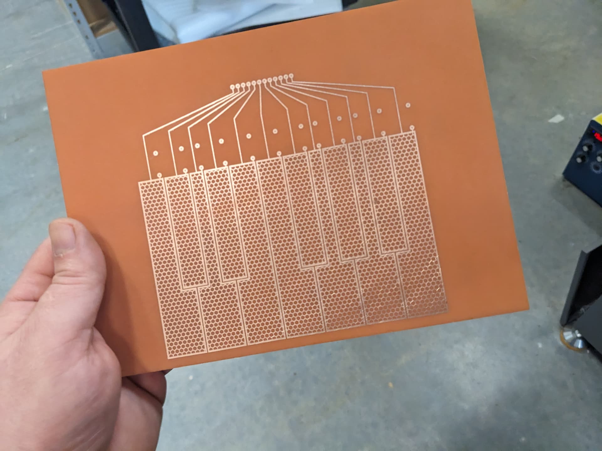

I printed and etched a one octave prototype at work yesterday. I’m using an arduino mega clone, and got some code and sensors working last night. it’s been about 5 years since I last coded an arduino so I’m basically relearning everything.
I also have a daisy seed sub module, which has 2 cv and 2 gate out. the plan is have the mega handle all the inputs to midi (in theory you could have up to 60 keys, but I’ll go with 37), and have the daisy recieve that midi and convert it to duo CV and gate or mono CV with modulation, and a midi din out. It’s the 64mb daisy so there’s a actually a lot of potential to do a lot more with it, act as a digital poly, process audio, etc. but midi to CV is good for now. The plan is to make this as a single large module (either 84 hp or 104 hp) that takes up the bottom row of a rack, kind of dreaming about the building something around the TipTop ART modules. I have most of the components for this already so about the only thing to source is a large blank copper clad board.
9 Likes
Looks great! Are you following some tutorial? I’ve been curious about making one myself but didn’t get to it yet. Also considering force-sensitive resistors instead
I’m kinda mangling the code in this version here to add the after touch etc. I haven’t seen too many tutorials on this yet, at least not clear ones, so I’m kinda mashing together what ever info I can find. I have a bunch of 2megohm resistors arriving today, which will let me hook up the full octave, and then I’m going to add a midi din port so that I can try it in different situations. since this will pass the midi over to the daisy seed I’m not going to bother with USB midi. I need to observe what actual midi messages are sent for the aftertouch, so I’ll hook the midi din up to an interface and watch on a monitor.
https://www.youtube.com/watch?v=4TDIbMwov6s&list=WL&index=25&t=628s
Here a little poke of your imaginary Elektronaut friend, if you mean polyAT or channelAftertouch then
polyAftertouch( ch,pitch,val ){ this.status=0xA0 | ch; this.uint8=pitch; this.uint8=val; },
aftertouch( ch,val ){ this.status=0xD0 | ch; this.uint8=val; }
Hope that gets it going for you
1 Like
Got midi din hooked up along with all 12 keys and things are basically working as it should. I started mocking up a 37 key version on two stacked double sided boards (4 layers), on 104hp. Got all the key to Arduino connections figured out, but need to start incorporating the daisy. Gonna get the Erica Synths breadboard to make life easier. I also found a Canadian supplier of 24x36" double sided boards, I could maybe squeeze 3-4 units out of one board (if any are left over after prototypes I could maybe offer them up to elektronaut users).
I wanted to see it IRL so I printed it to some scrap plastic. I’ve got a spare OLED display and a capacitive touch LCD display (maybe handled by the daisy, for mod and pitch bends) I’m planning on integrating, as well as some buttons. I’ve done resistive touch screen on a midi controller before so I can figure it out again.

7 Likes
Very fascinating project - thanks for sharing the journey!
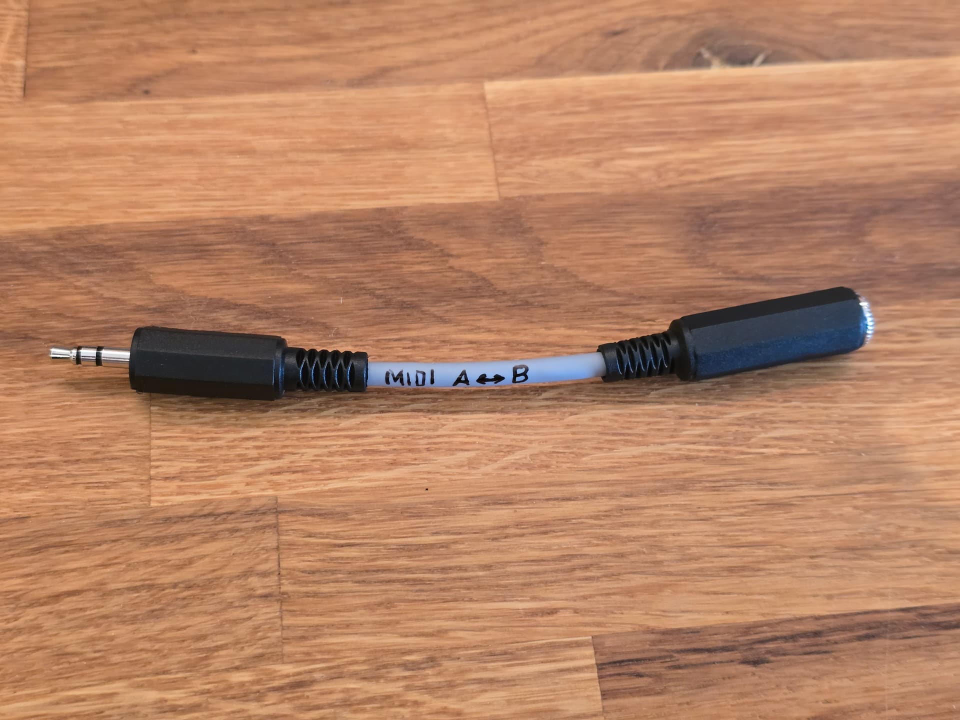
I don’t have much time for DIY electronics at the moment. The only thing I did today was make a TRS MIDI A ↔ B adapter cable because I couldn’t find one at a reasonable price online and in stock. Not sure if that even qualifies as DIY electronics ![]()
It was my first DIY cable. It works, but it wasn’t as fun to make as I had expected. I felt all thumbs, and it was pretty fiddly to connect and solder. So I think I’ll stick to DIY electronics projects and keep buying cables whenever possible.
6 Likes
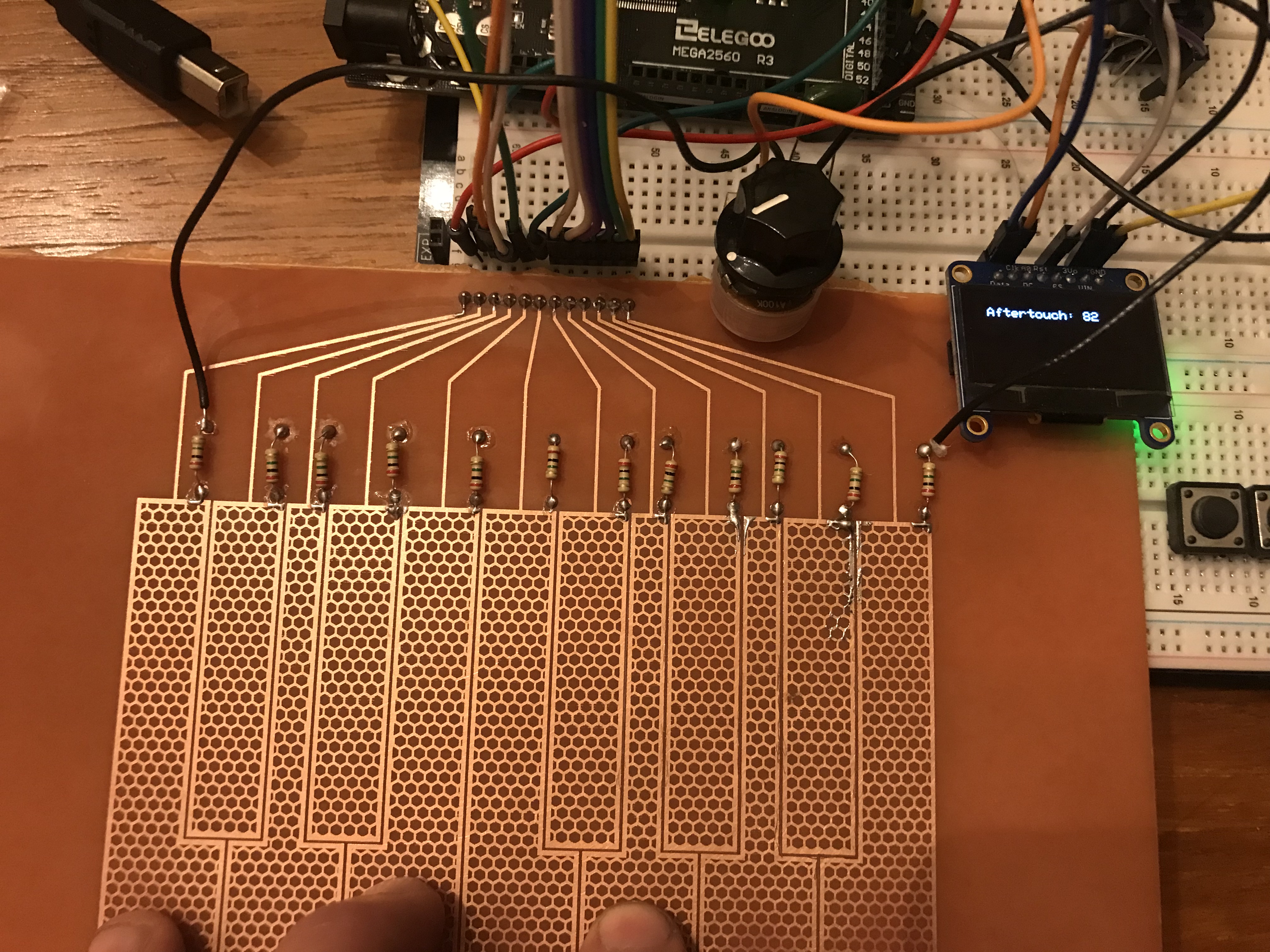
OLED integrated, showing aftertouch data at key press (I had it display live data but that was causing the aftertouch to pulse weirdly). Currently it’s channel aftertouch, which kinda sucks because with the capacitive keybed the more fingers on keys the higher the value. I guess it’s adding them all together. I have a Korg multi/poly which I believe can be set to respond to poly aftertouch, but I don’t want to move the breadboard downstairs to test it yet.
The potentiometer controls sensitivity, I’ll have to find space on my layout because it’s very handy.
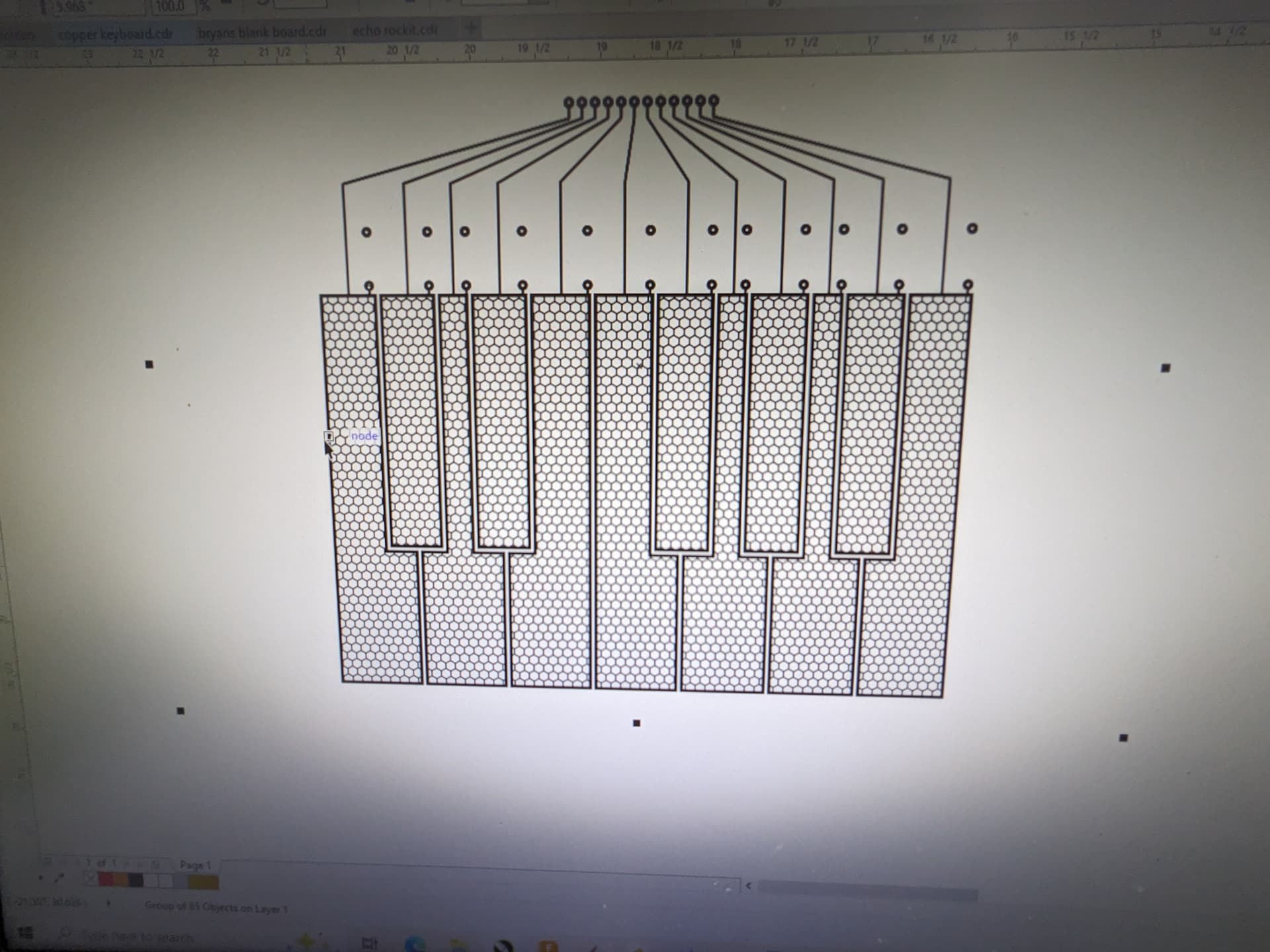
Next task is to incorporate buttons for octaves and midi channel. Then I have to make notes on my diagram on what pins I used, and where things need to change. I’m laying out all my traces manually in graphics software because I don’t know how to use EDE software and don’t want to learn YET another new thing ![]()
5 Likes
well certainly your hand is conductive therefor you shortcut the circuits, ergo the math must look different. Poly aftertouch would need to catch what value you can evaluate per ‘key’. So you might come close with some trickery, capturing value jumps or incorporate amount of keys simultaneous touched - isn’t it. I mean there is a reason why aftertouch on most keyboards is picked up by reading out pressure or pushed angle rather than energy flow. Which nails your challenge to some serious craft. So either you isolate the circuits to each other from your hand shortcutting them or you do a trick, in example read out with some sort of timeslot per key (aka a phase difference per key) basically ignoring the shortcutted, which has its pro and cons too.
I do actually get individual key readings, I believe the channel pressure adding all the key readings together is a fault of the arduino midi library. I just realized I have a soft synth that responds to poly aftertouch! The GForce VSM IV, I made the little change to the firmware to make it poly, and I can pulsate the filter cutoff by wiggling my fingers! it’s a subtle instrument so it’s filter is not extreme, but it seems to work.
1 Like
You could also just breadboard up some experiments with a grab bag of CMOS logic chips and some breadboards.
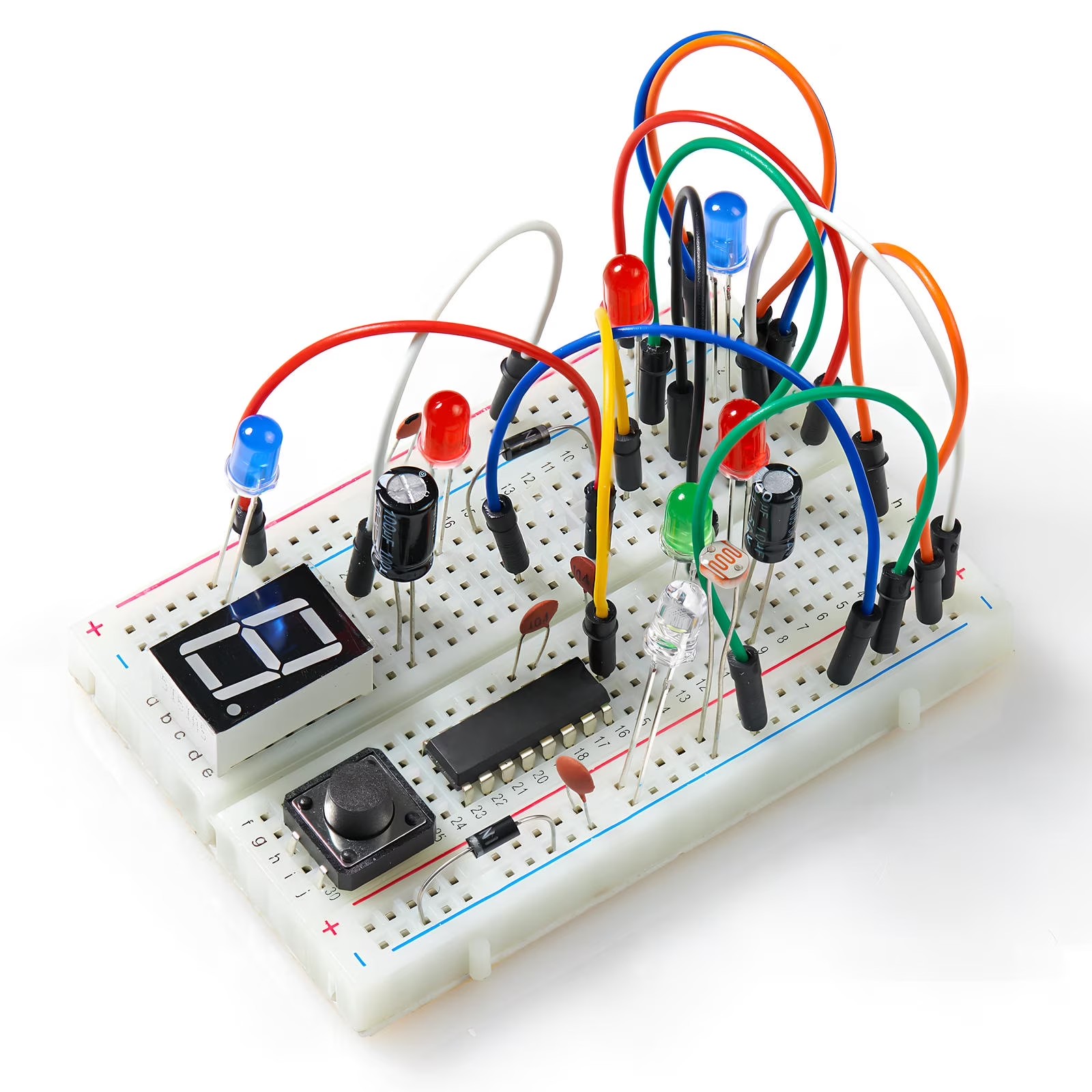
BTW ( ADDED ) :
This picture is pure baloney, a pretty picture. You can’t use a breadboard like this.
It’s nowhere near as permanent as a soldered up system, but a heck of a lot more flexible for experiments, more in keeping with Stanley Lunetta’s approach.
3 Likes
As far as doing Lunetta style synths of your own ( to get you ready to experiment ) there are a ton of on-line free guides.
Like :
You can also build sequencers this way too.
4 Likes
There’s also this browser based simulator:
3 Likes