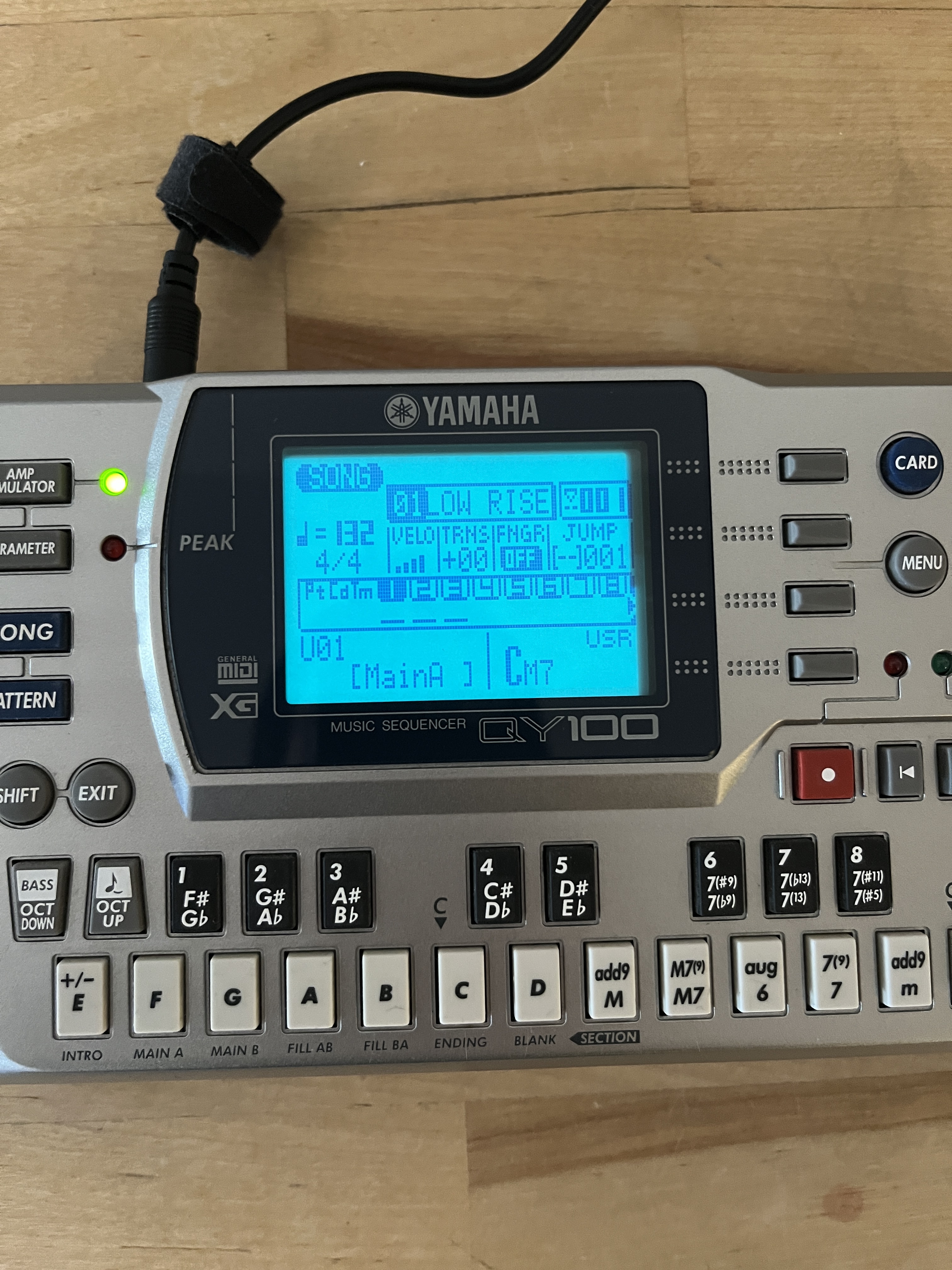
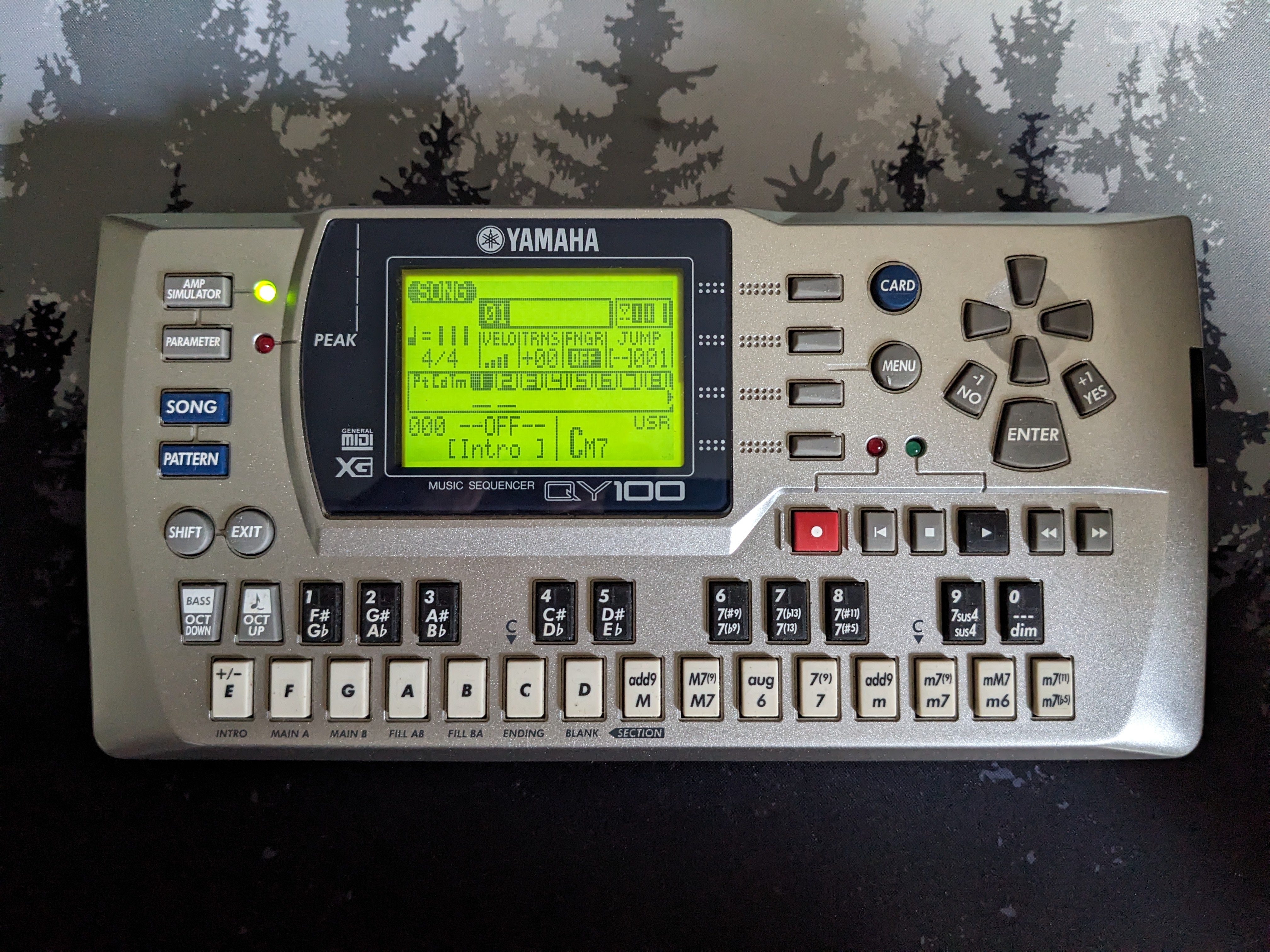
Just completed putting an EL panel behind the LCD.
Worked out pretty well and has a very legible glow in low lighting.
Actually is a yellow panel, but comes out green through the screen itself.
Little bit of soldering required and a slightly nervewracking peel-off of the reflective film on the back of the inside of the LCD module followed by accurate repositioning of the panel onto its pads. I didn’t (yet) bother with putting in a switch as I now always power from a ripcord and 5v powerbank.
Just reviving this topic because the Scope Eye instructions are a bit light on details regarding where and how to wire the EL panel, how to remove excess glue from the LCD, etc. I just recently did a mod of my QY100 to add an EL panel backlight to the screen.
The perfect place to wire in the inverter and panel is on the DMF50202N LCD board (see first image in link below). You’ll want to solder the black wire to ground on pin 7, the red and orange wires to +5v on pin 6, and the two white wires to the panel leads (see second and third image in link below).
Peeling the reflective foil off the back of the LCD isn’t as scary as folks make it sound, use tweezers. The LCD is robust and any artifacts that appear on the screen will eventually fade (see fourth and fifth image in link below). A lot of glue will be left on the LCD when you’re done. I let the entire LCD soak in 91% isopropyl alcohol for 15 minutes and then used my fingernail and cotton pads to scrape off the excess glue.
With the glue off you can place the LCD directly over the EL panel, but I chose to cut a small piece of matte frisket film to use as light diffusion between the panel and the LCD. Realigning the LCD is a pain with the extra elements underneath but you’ll get it eventually.
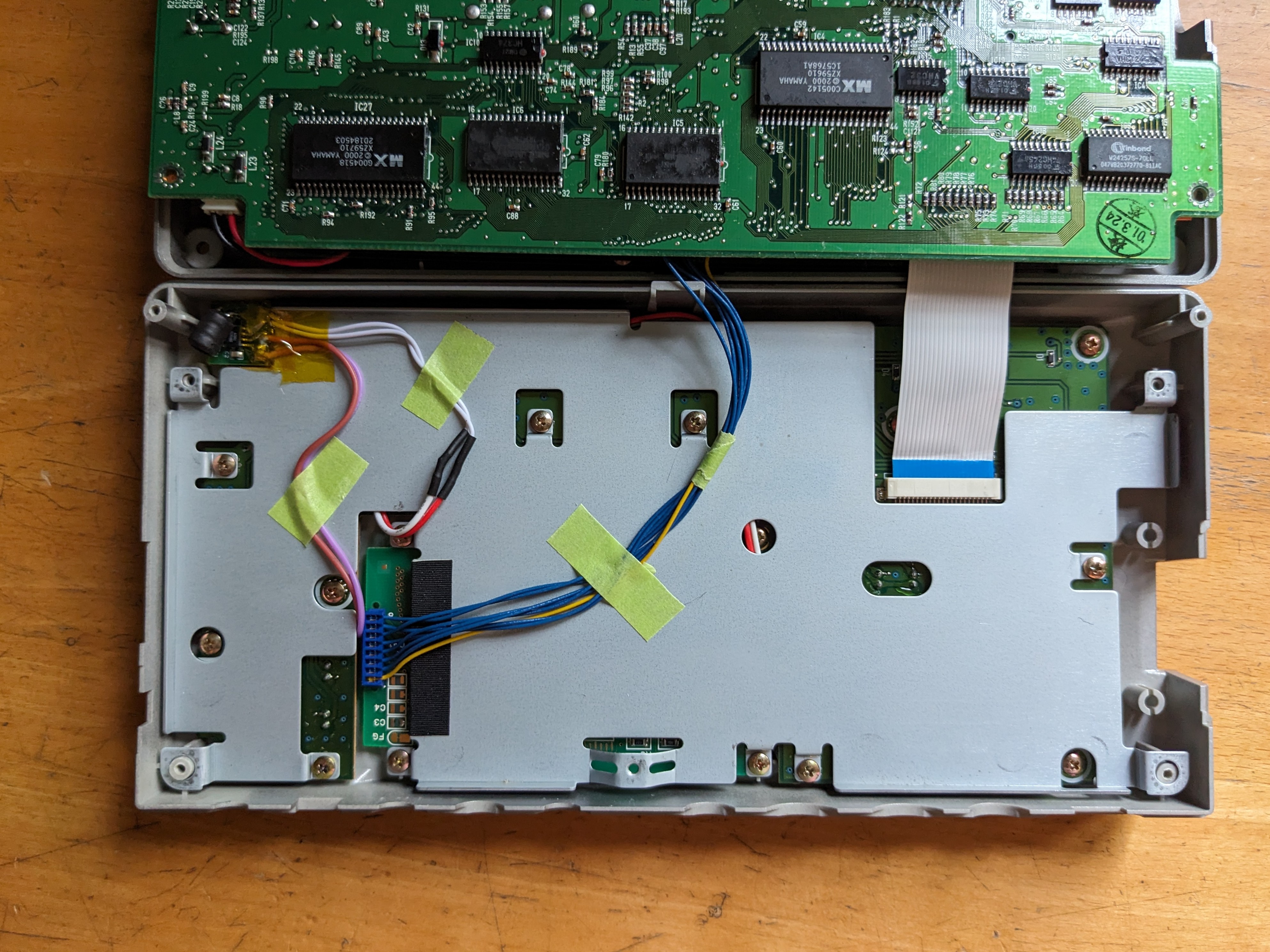
There aren’t a lot of good places for the inverter to live in the case, I chose to stick it in the upper left corner, underneath where the battery lead connects to the main board (see image six in link below). If you’re not careful, the inverter will cause AC noise to leak into the output, so make sure it’s not directly touching any of the other components in the case.
Final results are images seven and eight (link below). Have fun and good luck!
Thanks for this more detailed guide, and the pictures - I always wanted to do this to the QY70 I had back in the day but I sold it before I got the balls to follow through.
I just ordered a QY100 today and decided to see about backlighting and your post (and of course mokomo’s above) inspired me to order the parts myself. Thanks!
I had few issues with the screen, and I got lucky when peeling the reflective layer in that it left almost no glue behind. I also went without a layer of frisket masking film as I had none on hand/forgot to order some in time and I think it looks just fine without it.
My biggest difficulty was placing the inverter board… The wires it came with were not quite long enough to get it into place and I ended up having to take it all apart again and solder new wires on. As the two 5V wires are powered from the same point I just bridged the pads on the inverter board and only ran one wire. Works great!
I also thought about adding a switch but did not get around to it after I didn’t see a nice unobtrusive place to add one. It was highly unlikely I’d ever be using it with the backlight off anyways so I guess we’ll see how it goes.
Thanks to everyone who has posted their builds and tips so far, they’ve helped a lot! I’m so happy with how this turned out
It sounds like you didn’t realign the LCD properly when reseating it. This can be tricky because the EL panel adds a non-negligible amount of space between the LCD and the edge connections (you’ll notice “lines” on the edge of the LCD that are mirrored where it sits—those connections are meant to align and it takes some trial and error). Make sure you’re also then re-bending the metal tabs so that they have enough force to push those connections together even with the EL between the two pieces.
It’s been a little while since I did this but I think that means you didn’t align the pins on the front of the display with the back of it just right and you’ll need to try re-seating the LCD on its PCB. Same thing if you only get some of the display showing